Inst ToolsInst ToolsInst Tools
  • Courses
  • Automation
    • PLC
    • Control System
    • Safety System
    • Communication
    • Fire & Gas System
  • Instrumentation
    • Design
    • Pressure
    • Temperature
    • Flow
    • Level
    • Vibration
    • Analyzer
    • Control Valve
    • Switch
    • Calibration
    • Erection & Commissioning
  • Interview
    • Instrumentation
    • Electrical
    • Electronics
    • Practical
  • Q&A
    • Instrumentation
    • Control System
    • Electrical
    • Electronics
    • Analog Electronics
    • Digital Electronics
    • Power Electronics
    • Microprocessor
  • Request
Search
  • Books
  • Software
  • Projects
  • Process
  • Tools
  • Basics
  • Formula
  • Power Plant
  • Root Cause Analysis
  • Electrical Basics
  • Animation
  • Standards
  • 4-20 mA Course
  • Siemens PLC Course
Reading: Single Phase AC Induction Motors
Share
Font ResizerAa
Inst ToolsInst Tools
Font ResizerAa
  • Courses
  • Design
  • PLC
  • Interview
  • Control System
Search
  • Courses
  • Automation
    • PLC
    • Control System
    • Safety System
    • Communication
    • Fire & Gas System
  • Instrumentation
    • Design
    • Pressure
    • Temperature
    • Flow
    • Level
    • Vibration
    • Analyzer
    • Control Valve
    • Switch
    • Calibration
    • Erection & Commissioning
  • Interview
    • Instrumentation
    • Electrical
    • Electronics
    • Practical
  • Q&A
    • Instrumentation
    • Control System
    • Electrical
    • Electronics
    • Analog Electronics
    • Digital Electronics
    • Power Electronics
    • Microprocessor
  • Request
Follow US
All rights reserved. Reproduction in whole or in part without written permission is prohibited.
Inst Tools > Blog > Electrical Theory > Single Phase AC Induction Motors

Single Phase AC Induction Motors

Last updated: August 6, 2018 5:30 pm
Editorial Staff
Electrical Theory
No Comments
Share
1 Min Read
SHARE

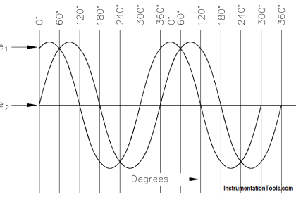
If two stator windings of unequal impedance are spaced 90 electrical degrees apart and connected in parallel to a single-phase source, the field produced will appear to rotate. This is called phase splitting.

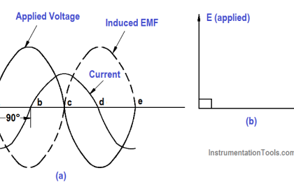
In a split-phase motor, a starting winding is utilized. This winding has a higher resistance and lower reactance than the main winding (below Figure). When the same voltage VT is applied to the starting and main windings, the current in the main winding (IM) lags behind the current of the starting winding IS ( as shown in Figure).

Split Phase Motor

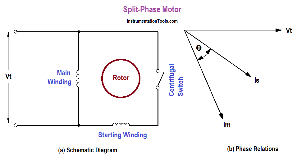
The angle between the two windings is enough phase difference to provide a rotating magnetic field to produce a starting torque. When the motor reaches 70 to 80% of synchronous speed, a centrifugal switch on the motor shaft opens and disconnects the starting winding.

Single-phase motors are used for very small commercial applications such as household appliances and buffers.

Don't Miss Our Updates
Be the first to get exclusive content straight to your email.
We promise not to spam you. You can unsubscribe at any time.
Invalid email address
You've successfully subscribed !

Continue Reading

Induction Motor Torque Versus Slip
DC Generator Theory
Methods of Producing Voltage (Electricity)
Full-Wave Rectifier Circuit
Block Diagram
Circuit Breaker Control Circuit
Share This Article
Facebook Whatsapp Whatsapp LinkedIn Copy Link
Share
Leave a Comment

Leave a Reply Cancel reply

Your email address will not be published. Required fields are marked *

Stay Connected

128.3kFollowersLike
69.1kFollowersFollow
210kSubscribersSubscribe
38kFollowersFollow

Categories

Explore More

Motor Controllers
Wattmeter
Impedance in RC Circuits
Transformer Operation Under No-Load
Resonance, Resonant Frequency, Series and Parallel Resonance
Battery Operation : Series and Parallel
Impedance
Low Voltage Air Circuit Breaker Principle

Keep Learning

Current Law

Applying Kirchhoff’s Current Law

Wiring Diagram

Wiring Diagram

What is electrical transformer

Transformer Impedance Ratio

Voltage Polarities

Voltage Polarity and Current Direction

Series Parallel Circuit Analysis

Series – Parallel Circuit Analysis

Three-Phase Wye Wiring System

4-Wire, Three-Phase Wye Wiring System

Calculate Power in Parallel RL Circuit

Calculate Power in Parallel RL Circuit

Armature Current in a DC Motor

DC Motor Torque

Learn More

PLC Program for Counting Objects on Conveyor

PLC Program for Counting Moving Objects on Conveyor

How to Filter Digital and Analog Inputs in a PLC

#7 PLC Best Practices – Validate and Alert for Paired Inputs/Outputs

Redundant Power Supply

How Does Redundant Power Supply Work?

circuit-breaker-working-principle-animation

Circuit Breaker Working Principle Animation

Top 100 PLC Objective Questions and Answers

Top 100 PLC Objective Questions and Answers

Frequency Division Multiplexers Objective Questions

Frequency Division Multiplexers Objective Questions

Coriolis mass flowmeter Density Measurement

How Coriolis Mass Flow Meter Measure Density?

Electromagnetic Fields Objective Questions

Electromagnetic Field Theory Questions and Answers

Menu

  • About
  • Privacy Policy
  • Copyright

Quick Links

  • Learn PLC
  • Helping Hand
  • Part Time Job

YouTube Subscribe

Follow US
All rights reserved. Reproduction in whole or in part without written permission is prohibited.
Welcome Back!

Sign in to your account

Username or Email Address
Password

Lost your password?