Inst ToolsInst ToolsInst Tools
  • Courses
  • Automation
    • PLC
    • Control System
    • Safety System
    • Communication
    • Fire & Gas System
  • Instrumentation
    • Design
    • Pressure
    • Temperature
    • Flow
    • Level
    • Vibration
    • Analyzer
    • Control Valve
    • Switch
    • Calibration
    • Erection & Commissioning
  • Interview
    • Instrumentation
    • Electrical
    • Electronics
    • Practical
  • Q&A
    • Instrumentation
    • Control System
    • Electrical
    • Electronics
    • Analog Electronics
    • Digital Electronics
    • Power Electronics
    • Microprocessor
  • Request
Search
  • Books
  • Software
  • Projects
  • Process
  • Tools
  • Basics
  • Formula
  • Power Plant
  • Root Cause Analysis
  • Electrical Basics
  • Animation
  • Standards
  • 4-20 mA Course
  • Siemens PLC Course
Reading: High Voltage Circuit Breaker Principle
Share
Font ResizerAa
Inst ToolsInst Tools
Font ResizerAa
  • Courses
  • Design
  • PLC
  • Interview
  • Control System
Search
  • Courses
  • Automation
    • PLC
    • Control System
    • Safety System
    • Communication
    • Fire & Gas System
  • Instrumentation
    • Design
    • Pressure
    • Temperature
    • Flow
    • Level
    • Vibration
    • Analyzer
    • Control Valve
    • Switch
    • Calibration
    • Erection & Commissioning
  • Interview
    • Instrumentation
    • Electrical
    • Electronics
    • Practical
  • Q&A
    • Instrumentation
    • Control System
    • Electrical
    • Electronics
    • Analog Electronics
    • Digital Electronics
    • Power Electronics
    • Microprocessor
  • Request
Follow US
All rights reserved. Reproduction in whole or in part without written permission is prohibited.
Inst Tools > Blog > Electrical Theory > High Voltage Circuit Breaker Principle

High Voltage Circuit Breaker Principle

Last updated: August 16, 2018 2:48 pm
Editorial Staff
Electrical Theory
No Comments
Share
3 Min Read
SHARE

High-voltage circuit breakers (including breakers rated at intermediate voltage) are used for service on circuits with voltage ratings higher than 600 volts. Standard voltage ratings for these circuit breakers are from 4,160 to 765,000 volts and three-phase interrupting ratings of 50,000 to 50,000,000 kVA.

In the early stages of electrical system development, the major portion of high-voltage circuit breakers were oil circuit breakers. However, magnetic and compressed-air type air circuit breakers have been developed and are in use today.

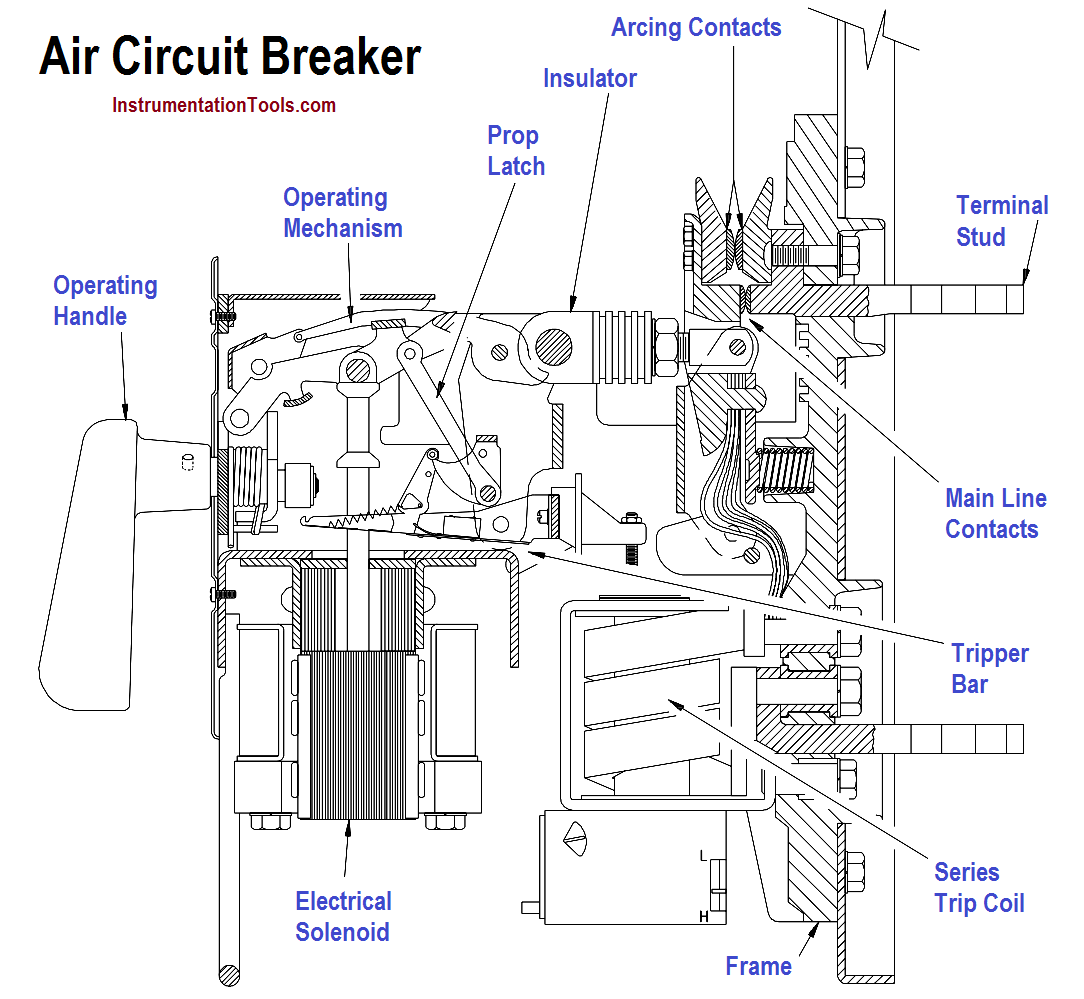
The magnetic air circuit breaker is rated up to 750,000 kVA at 13,800 volts. This type of circuit breaker interrupts in air between two separable contacts with the aid of magnetic blowout coils. As the current-carrying contacts separate during a fault condition, the arc is drawn out horizontally and transferred to a set of arcing contacts. Simultaneously, the blowout coil provides a magnetic field to draw the arc upward into the arc chutes. The arc, aided by the blowout coil magnetic field and thermal effects, accelerates upward into the arc chute, where it is elongated and divided into many small segments.

The construction of this type of circuit breaker is similar to that of a large air circuit breaker used for low-voltage applications, except that they are all electrically operated.

Compressed-Air Circuit Breakers or Air-Blast Circuit Breakers

Compressed-air circuit breakers, or air-blast circuit breakers, depend on a stream of compressed air directed toward the separable contacts of the breaker to interrupt the arc formed when the breaker is opened.

Air-blast circuit breakers have recently been developed for use in extra high-voltage applications with standard ratings up to 765,000 volts.

Oil Circuit Breakers (OCB)

Oil circuit breakers (OCBs) are circuit breakers that have their contacts immersed in oil. Current interruption takes place in oil which cools the arc developed and thereby quenches the arc.

The poles of small oil circuit breakers can be placed in one oil tank; however, the large high-voltage circuit breakers have each pole in a separate oil tank.

The oil tanks in oil circuit breakers are normally sealed. The electrical connections between the contacts and external circuits are made through porcelain bushings.

Air Circuit Breaker Principle

Don't Miss Our Updates
Be the first to get exclusive content straight to your email.
We promise not to spam you. You can unsubscribe at any time.
Invalid email address
You've successfully subscribed !

Continue Reading

Transformer Voltage Ratio
Calculate Power in Parallel RC Circuit
Electric Circuit : Open & Short Circuits
Compound Generators
Impedance
DC Circuit Analysis Node Equations
Share This Article
Facebook Whatsapp Whatsapp LinkedIn Copy Link
Share
Leave a Comment

Leave a Reply Cancel reply

Your email address will not be published. Required fields are marked *

Stay Connected

128.3kFollowersLike
69.1kFollowersFollow
210kSubscribersSubscribe
38kFollowersFollow

Categories

Explore More

Series and Parallel Inductors
Applying Kirchhoff’s Voltage Law
Power Triangle
DC Motor Connections
Transformer Turns Ratio
Voltmeters
Calculate Power in Parallel RCL Circuit
Shunt-Wound DC Generators

Keep Learning

Ammeter with Shunt

Ammeter

Three Phase Transformer Connections

Three Phase Transformer Connections

Battery Hazard

Battery Hazards

Units of Electrical Measurement

Units of Electrical Measurement

Ohm Meter Circuit

Ohm Meter

4-Wire, Three-Phase Delta Wiring System

4-Wire, Three-Phase Delta Wiring System

Transformer Efficiency and Loses Formula

Transformer Losses and Efficiency

Parallel Circuit

Parallel Circuit

Learn More

What is a Laser Sensor

What is a Laser Sensor? Principle

Types of Failures in Industrial Automation Systems

Types of Failures in Industrial Automation Systems

Digital Electronics Multiple Choice Questions

Boolean Logic Operations Objective Questions

What is a Process Alarm

What is a Process Alarm? Types of Alarms

spiral bourdon tube

Bellows, Diaphragms and Bourdon Tubes

Tank Gauging Measurement

Purpose of Tank Gauging Level Measurement

Catalytic-Bead-Sensor-2

Gas Detectors Working Principle

Difference between Signal Cables and Control Cables

Difference between Signal Cables and Control Cables

Menu

  • About
  • Privacy Policy
  • Copyright

Quick Links

  • Learn PLC
  • Helping Hand
  • Part Time Job

YouTube Subscribe

Follow US
All rights reserved. Reproduction in whole or in part without written permission is prohibited.
Welcome Back!

Sign in to your account

Username or Email Address
Password

Lost your password?