Inst ToolsInst ToolsInst Tools
  • Courses
  • Automation
    • PLC
    • Control System
    • Safety System
    • Communication
    • Fire & Gas System
  • Instrumentation
    • Design
    • Pressure
    • Temperature
    • Flow
    • Level
    • Vibration
    • Analyzer
    • Control Valve
    • Switch
    • Calibration
    • Erection & Commissioning
  • Interview
    • Instrumentation
    • Electrical
    • Electronics
    • Practical
  • Q&A
    • Instrumentation
    • Control System
    • Electrical
    • Electronics
    • Analog Electronics
    • Digital Electronics
    • Power Electronics
    • Microprocessor
  • Request
Search
  • Books
  • Software
  • Projects
  • Process
  • Tools
  • Basics
  • Formula
  • Power Plant
  • Root Cause Analysis
  • Electrical Basics
  • Animation
  • Standards
  • 4-20 mA Course
  • Siemens PLC Course
Reading: Series – Parallel Circuit Analysis
Share
Notification Show More
Font ResizerAa
Inst ToolsInst Tools
Font ResizerAa
  • Courses
  • Design
  • PLC
  • Interview
  • Control System
Search
  • Courses
  • Automation
    • PLC
    • Control System
    • Safety System
    • Communication
    • Fire & Gas System
  • Instrumentation
    • Design
    • Pressure
    • Temperature
    • Flow
    • Level
    • Vibration
    • Analyzer
    • Control Valve
    • Switch
    • Calibration
    • Erection & Commissioning
  • Interview
    • Instrumentation
    • Electrical
    • Electronics
    • Practical
  • Q&A
    • Instrumentation
    • Control System
    • Electrical
    • Electronics
    • Analog Electronics
    • Digital Electronics
    • Power Electronics
    • Microprocessor
  • Request
Follow US
All rights reserved. Reproduction in whole or in part without written permission is prohibited.
Inst Tools > Blog > Electrical Theory > Series – Parallel Circuit Analysis

Series – Parallel Circuit Analysis

Last updated: July 25, 2018 4:33 pm
Editorial Staff
Electrical Theory
No Comments
Share
2 Min Read
SHARE

When solving for voltage, current, and resistance in a series-parallel circuit, follow the rules which apply to the series part of the circuit, and follow the rules which apply to the parallel part of the circuit.

Solving these circuits can be simplified by reducing the circuit to a single equivalent resistance circuit, and redrawing the circuit in simplified form. The circuit is then called an equivalent circuit (Figure 46).

Series Parallel Circuit Analysis

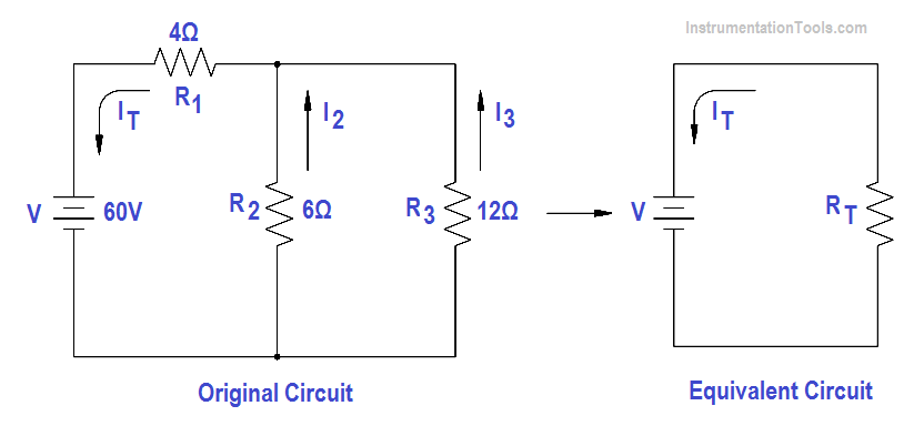
Figure 46 Redrawn Circuit Example

The easiest way to solve these types of circuits is to do it in steps.

Step 1: Find the equivalent resistance of the parallel branch:

Rp = (R2 R3 )/(R2+R3)

Rp = (6×12)/(6+12)

Rp = 72/18 = 4Ω

Step 2: Find the resistance of the equivalent series circuit:

RT = R1 +Rp  = 4 + 4 = 8Ω

Step 3: Find total current (IT)

 IT = V / RT = 60/8 = 7.5 amps

Step 4: Find I2 and I3 . The voltage across R1 and R2 is equal to the applied voltage (V), minus the voltage drop across R1.

V2 = V3 = V – IT R1 = 60 – (7.5 x 4) = 30V

Then, I2 and I3 are calculated.

I2 = V2/R2 = 30/6 = 5 amps

I3 = V3/R3 = 30/12 = 2.5 amps

Don't Miss Our Updates
Be the first to get exclusive content straight to your email.
We promise not to spam you. You can unsubscribe at any time.
Invalid email address
You've successfully subscribed !

Continue Reading

Single Phase Power Wiring Schemes
3-Wire, Three-Phase Delta Wiring System
Transformer Turns Ratio
4-Wire, Three-Phase Delta Wiring System
Battery Operation : Series and Parallel
AC Generator Nameplate Ratings
Share This Article
Facebook Whatsapp Whatsapp LinkedIn Copy Link
Share
Leave a Comment

Leave a Reply Cancel reply

Your email address will not be published. Required fields are marked *

Stay Connected

128.3kFollowersLike
69.1kFollowersFollow
210kSubscribersSubscribe
38kFollowersFollow

Categories

Explore More

Magnetism
Block Diagram
Electrical Wiring Terminology
Power Factor
Power in Balanced 3 Phase Loads
Calculate Power in Series RCL Circuit
Parallel Short Circuit Faults
Parallel Circuit Current Calculations

Keep Learning

Calculate Power in Parallel RL Circuit

Calculate Power in Parallel RL Circuit

Single Phase Motor Manual Controller

Motor Controllers

Synchronous Motor Principle

Synchronous Motors

Types of Capacitors

Types of Capacitors

How to Measure Specific Gravity of Battery

How to Measure Specific Gravity of Battery

Unbalanced 3 Phase Loads

Unbalanced 3 Phase Loads

Left-Hand Rule for Generators

DC Generator Theory

Two Wattmeters to Measure 3 Phase Power

Three Phase Wattmeter

Learn More

Process Variable Damping Graph

Process Variable Damping of Transmitter

Digital Electronics Multiple Choice Questions

Master-Slave Flip-Flops Objective Questions

Top 100 Robotic Projects for Engineering Students

Top 100 Robotic Projects for Engineering Students

Automation in Agriculture

Automation in Farming & Agriculture

Level Transmitter configuration in PLC

Scaling with Parameters (SCP) Instruction in PLC

Hydrostatic level transmitter Formula

Hydrostatic Level Transmitter Questions

Motor Maintenance

Motor Maintenance, Troubles, Regular Checks, Performance

Faceplate in WinCC

Siemens HMI Training – Using UDTs with Faceplates

Menu

  • About
  • Privacy Policy
  • Copyright

Quick Links

  • Learn PLC
  • Helping Hand
  • Part Time Job

YouTube Subscribe

Follow US
All rights reserved. Reproduction in whole or in part without written permission is prohibited.
Welcome Back!

Sign in to your account

Username or Email Address
Password

Lost your password?