Inst ToolsInst ToolsInst Tools
  • Courses
  • Automation
    • PLC
    • Control System
    • Safety System
    • Communication
    • Fire & Gas System
  • Instrumentation
    • Design
    • Pressure
    • Temperature
    • Flow
    • Level
    • Vibration
    • Analyzer
    • Control Valve
    • Switch
    • Calibration
    • Erection & Commissioning
  • Interview
    • Instrumentation
    • Electrical
    • Electronics
    • Practical
  • Q&A
    • Instrumentation
    • Control System
    • Electrical
    • Electronics
    • Analog Electronics
    • Digital Electronics
    • Power Electronics
    • Microprocessor
  • Request
Search
  • Books
  • Software
  • Projects
  • Process
  • Tools
  • Basics
  • Formula
  • Power Plant
  • Root Cause Analysis
  • Electrical Basics
  • Animation
  • Standards
  • 4-20 mA Course
  • Siemens PLC Course
Reading: Scaling Sensor Output to Engineering Units
Share
Notification Show More
Font ResizerAa
Inst ToolsInst Tools
Font ResizerAa
  • Courses
  • Design
  • PLC
  • Interview
  • Control System
Search
  • Courses
  • Automation
    • PLC
    • Control System
    • Safety System
    • Communication
    • Fire & Gas System
  • Instrumentation
    • Design
    • Pressure
    • Temperature
    • Flow
    • Level
    • Vibration
    • Analyzer
    • Control Valve
    • Switch
    • Calibration
    • Erection & Commissioning
  • Interview
    • Instrumentation
    • Electrical
    • Electronics
    • Practical
  • Q&A
    • Instrumentation
    • Control System
    • Electrical
    • Electronics
    • Analog Electronics
    • Digital Electronics
    • Power Electronics
    • Microprocessor
  • Request
Follow US
All rights reserved. Reproduction in whole or in part without written permission is prohibited.
Inst Tools > Blog > Formulas > Scaling Sensor Output to Engineering Units

Scaling Sensor Output to Engineering Units

Last updated: April 19, 2019 1:29 pm
Editorial Staff
Formulas Pressure Measurement
No Comments
Share
2 Min Read
SHARE

Sensor Scaling – Converting Current and Voltage Inputs To Engineering Units Such As psi, Deg C, m3/hr etc…

Scaling Sensor Output to Engineering Units

Sensor Scaling

It is very often necessary to convert a voltage, millivot or current reading into a more useful value such as PSI, m3/hr, DegC, etc. For example, if measuring temperature using a Thermocouple, it would be provided to the user in Deg C instead of millivolts, which is what the thermocouple typically produces.

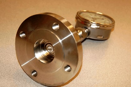
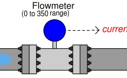
Other examples would be using a pressure transducer to measure PSI, a flow sensor to measure m3/hr.

It is very simple to scale any sensor, and the same equation applies to all methods of data display and acquisition. First, the formula:

Y=MX+B

Where Y is the output or ENGINEERING UNITS
Where M is the slope or the SCALE FACTOR
Where X is the INPUT (millivolts, volts, etc) and
Where B is the OFFSET

Example

Here is a typical example where a pressure sensor is used to measure 0-500 PSI and the output is 1-5Vdc.

First, using the Y=MX+B formula, we determine what each value is in order to calculate for Y.

X = 4 (since 1-5V has a span of 4 volts. If it was a 0-10Vdc output, X would be 10)

M = 125 (use divide the Units by the Voltage or Current – 0-500/1-5 = 125) which results in PSI/Volts

B = -125 ( since the output starts at 1 volt, there is an offset.

We calculated a value of 125 PSI/Volt, therefore, 1V = -125)

If the output of the sensor was 0-5Vdc, then there would be no offset.

To test that the values are correct, put them in the equation.

5 volts out should give us 500PSI and 1 volt out should give us 0 PSI.

Y=125(5) + (-125) = 500PSI
Y=125(1) + (-125) = 0 PSI

That’s it.

Don't Miss Our Updates
Be the first to get exclusive content straight to your email.
We promise not to spam you. You can unsubscribe at any time.
Invalid email address
You've successfully subscribed !

Continue Reading

Pressure Gauges : Common Causes for Failures and Their Effective Solutions
How much Pressure applied to U-tube Water Manometer?
Installation and Calibration of Pressure Transmitter
Bellows Pressure Sensors Working Principle Animation
Pressure and Temperature Gauges
Difference Between Absolute and Gauge Pressure
Share This Article
Facebook Whatsapp Whatsapp LinkedIn Copy Link
Share
Leave a Comment

Leave a Reply Cancel reply

Your email address will not be published. Required fields are marked *

Stay Connected

128.3kFollowersLike
69.1kFollowersFollow
210kSubscribersSubscribe
38kFollowersFollow

Categories

Explore More

Instrumentation Basics – Range Conversion Formula and Examples
Differential Pressure Sensors Calibration Procedure
Pressure Gauge Problems
What are Pressure Sensing Lines? – Causes of Errors in Measurement
Differential Pressure Transmitter Calibration Procedure
Formula for Current 4-20ma to Percentage Conversion
Pneumatic Pressure Transmitters Principle
Linear to Square Root Extraction

Keep Learning

Differential Pressure Switch Principle

Differential Pressure Switch Principle

How to Connect HART Communicator with DP Transmitter

15 HART Communicator Questions

Pressure Gauge with Block and Bleed Valves

Pressure Gauge with Block and Bleed Valves

Bellow Principle

Bellows

Remote Diaphragm Seal Transmitter for Vacuum Application

Remote Diaphragm Seal Transmitter for Vacuum Application

Differential Pressure Gauge Principle

Piston Type Differential Pressure Gauge Principle

pressure-switch-calibration-procedure

Pressure Switch Calibration Procedure

Pressure gauges with capsule elements

Pressure Gauges with Capsule Sensor Principle

Learn More

Edge Detection in PLC

Edge Detection in PLC Programming

Pressure gauge mechanism

How Measurement Span of Pressure Gauge Could be Changed?

Two Wire RTD Lead Wire Resistance Error

Temperature Error of 2-Wire, 3-Wire & 4-Wire RTD

Switches, Repeaters, Bridges, Routers, Firewalls

Purpose of Gateways, Bridges & Routers in Networking

SR Flip Flop Logic

How to implement SR Flip Flop using PLC Ladder Logic

Control Valve Positioner Working Principle

Control Valve Positioner Working Principle

Components of Bourdon Tube Pressure Gauge

Components of Bourdon Tube – Questions and Answers

Pressure and Temperature Compensation for Flow Transmitter

Why Pressure & Temperature Compensation required for Orifice Flow Meters ?

Menu

  • About
  • Privacy Policy
  • Copyright

Quick Links

  • Learn PLC
  • Helping Hand
  • Part Time Job

YouTube Subscribe

Follow US
All rights reserved. Reproduction in whole or in part without written permission is prohibited.
Welcome Back!

Sign in to your account

Username or Email Address
Password

Lost your password?