Inst ToolsInst ToolsInst Tools
  • Courses
  • Automation
    • PLC
    • Control System
    • Safety System
    • Communication
    • Fire & Gas System
  • Instrumentation
    • Design
    • Pressure
    • Temperature
    • Flow
    • Level
    • Vibration
    • Analyzer
    • Control Valve
    • Switch
    • Calibration
    • Erection & Commissioning
  • Interview
    • Instrumentation
    • Electrical
    • Electronics
    • Practical
  • Q&A
    • Instrumentation
    • Control System
    • Electrical
    • Electronics
    • Analog Electronics
    • Digital Electronics
    • Power Electronics
    • Microprocessor
  • Request
Search
  • Books
  • Software
  • Projects
  • Process
  • Tools
  • Basics
  • Formula
  • Power Plant
  • Root Cause Analysis
  • Electrical Basics
  • Animation
  • Standards
  • 4-20 mA Course
  • Siemens PLC Course
Reading: Battery Operation : Series and Parallel
Share
Font ResizerAa
Inst ToolsInst Tools
Font ResizerAa
  • Courses
  • Design
  • PLC
  • Interview
  • Control System
Search
  • Courses
  • Automation
    • PLC
    • Control System
    • Safety System
    • Communication
    • Fire & Gas System
  • Instrumentation
    • Design
    • Pressure
    • Temperature
    • Flow
    • Level
    • Vibration
    • Analyzer
    • Control Valve
    • Switch
    • Calibration
    • Erection & Commissioning
  • Interview
    • Instrumentation
    • Electrical
    • Electronics
    • Practical
  • Q&A
    • Instrumentation
    • Control System
    • Electrical
    • Electronics
    • Analog Electronics
    • Digital Electronics
    • Power Electronics
    • Microprocessor
  • Request
Follow US
All rights reserved. Reproduction in whole or in part without written permission is prohibited.
Inst Tools > Blog > Electrical Theory > Battery Operation : Series and Parallel

Battery Operation : Series and Parallel

Last updated: July 27, 2018 4:40 pm
Editorial Staff
Electrical Theory
No Comments
Share
6 Min Read
SHARE

Once the basic theory behind the operation of batteries is understood, we can apply these concepts to better understand the way batteries are utilized.

Series Cells

When several cells are connected in series (Figure 7), the total voltage output of the battery is equal to the sum of the individual cell voltages. In the example of the battery in Figure 7, the four 1.5V cells provide a total of 6 volts.

When we connect cells in series, the positive terminal of one cell is connected to the negative terminal of the next cell. The current flow through a battery connected in series is the same as for one cell.

Batteries Connected in Series

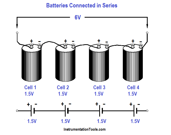
Figure 7 : Cells Connected in Series

Parallel Cells

Cells connected in parallel (Figure 8), give the battery a greater current capacity. When cells are connected in parallel, all the positive terminals are connected together, and all the negative terminals are connected together. The total voltage output of a battery connected in parallel is the same as that of a single cell.

Cells connected in parallel have the same effect as increasing the size of the electrodes and electrolyte in a single cell. The advantage of connecting cells in parallel is that it will increase the current-carrying capability of the battery.

Batteries Connected in Parallel

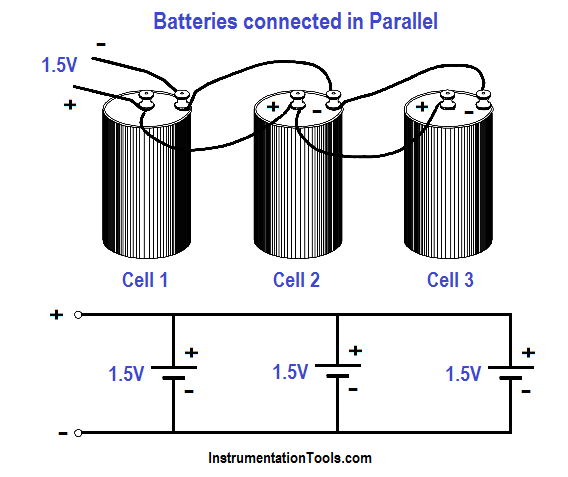
Figure 8 : Cells Connected in Parallel

Primary Cell

Cells that cannot be returned to good condition, or recharged after their voltage output has dropped to a value that is not usable, are called primary cells. Dry cells that are used in flashlights and transistor radios (e.g., AA cells, C cells) are examples of primary cells.

Secondary Cells

Cells that can be recharged to nearly their original condition are called secondary cells. The most common example of a secondary, or rechargeable cell, is the lead-acid automobile battery.

Capacity

The capacity of a storage battery determines how long the storage battery will operate at a certain discharge rate and is rated in ampere-hours. For example, a 120 ampere-hour battery must be recharged after 12 hours if the discharge rate is 10 amps.

Internal Resistance

Internal resistance in a chemical cell is due mainly to the resistance of the electrolyte between electrodes (Figure 9).

Any current in the battery must flow through the internal resistance. The internal resistance is in series with the voltage of the battery, causing an internal voltage drop (Figure 10).

With no current flow, the voltage drop is zero; thus, the full battery voltage is developed across the output terminals (VB).  If a load is placed on the battery, load resistance (RL) is in series with internal resistance (Ri).

Internal Resistance in a Chemical Cell

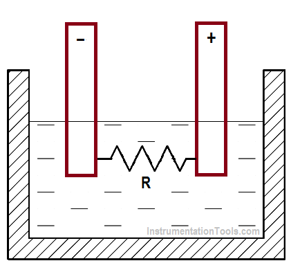
Figure 9 : Internal Resistance in a Chemical Cell

Battery Internal Voltage Drop

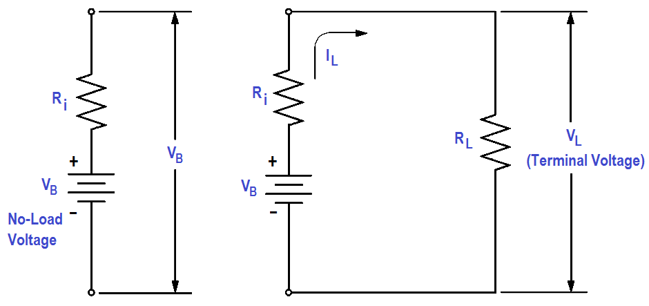
Figure 10 : Internal Voltage Drop

When current flows in the circuit (IL ), the internal voltage drop (ILRi) drops the terminal voltage of the battery as shown in below Equation. Thus, internal resistance reduces both the current and voltage available to the load.

VL = VB – ILRi

Shelf Life

The shelf life of a battery is the time which a battery may be stored and not lose more than 10 percent of its original capacity.

Charge and Discharge

The charge of a battery may refer to as one of two things:

  1. the relative state of capacity of the battery, or
  2. the actual act of applying current flow in the reverse direction to return the battery to a fully-charged state.

Discharge, simply stated, is the act of drawing current from a battery.

Battery Operations Summary

  • The output voltage of a battery connected in series is equal to the sum of the cell voltages.
  • A battery that is connected in parallel has the advantage of a greater current carrying capability.
  • Secondary cells can be recharged; primary cells cannot be recharged.
  • The unit for battery capacity is the ampere-hour.
  • Internal resistance in a battery will decrease the battery voltage when a load is placed on the battery.
  • Shelf life is a term that is used to measure the time that a battery may sit idle and not lose more than 10 percent of its charge.
  • The charge of a battery may refer to one of two things: (1) the relative state of capacity of the battery, or (2) the actual act of applying current flow in the reverse direction to restore the battery to a fully-charged condition.
  • Discharge refers to the act of drawing current from a battery.
Don't Miss Our Updates
Be the first to get exclusive content straight to your email.
We promise not to spam you. You can unsubscribe at any time.
Invalid email address
You've successfully subscribed !

Continue Reading

Types of AC Generators
Rectifiers, Forward Bias and Reverse Bias
Capacitor
Types of Batteries
Single Phase AC Induction Motors
Shunt-Wound DC Generators
Share This Article
Facebook Whatsapp Whatsapp LinkedIn Copy Link
Share
Leave a Comment

Leave a Reply Cancel reply

Your email address will not be published. Required fields are marked *

Stay Connected

128.3kFollowersLike
69.1kFollowersFollow
210kSubscribersSubscribe
38kFollowersFollow

Categories

Explore More

Batteries
Capacitive Time Constant
Wiring Diagram
Transformer Turns Ratio
DC Generator Theory
Starting a Synchronous Motor
Capacitance and Capacitive Reactance
Moving Iron Vane Meter Movement

Keep Learning

Electrical Wiring Terminology

Electrical Wiring Terminology

LVR Motor Controller Operation

Low Voltage Protection (LVP) and Low Voltage Release (LVR)

Left-Hand Rule for Generators

Starting of DC Motors

Single Phase Motor Manual Controller

Motor Controllers

Circuit Breaker Control Circuit Wiring

Circuit Breaker Control Circuit

Air Circuit Breaker Principle

High Voltage Circuit Breaker Principle

Current Law

Applying Kirchhoff’s Current Law

Motor Rotating Magnetic Field

AC Motor Theory

Learn More

Level Transmitter

What is a Bridle?

Difference Between CNC Machine and VMC Machine

Difference Between CNC Machine and VMC Machine

Control Speed of an Induction Motor using Analog Output of PLC

Control Speed of Induction Motor using Analog Output of PLC

Location of Pressure Taps

Design Considerations of Orifice Plate

Infrared Hydrocarbon Gas Detector Calibration Procedure

Infrared Hydrocarbon Gas Detector Calibration Procedure

RTD Graph

Calculate Temperature Coefficient of RTD

Field Instrument package

Package System Architecture – Control & Instrumentation

Differential Pressure Sensor for Filtration Monitoring

Differential Pressure Sensor for Filtration Monitoring

Menu

  • About
  • Privacy Policy
  • Copyright

Quick Links

  • Learn PLC
  • Helping Hand
  • Part Time Job

YouTube Subscribe

Follow US
All rights reserved. Reproduction in whole or in part without written permission is prohibited.
Welcome Back!

Sign in to your account

Username or Email Address
Password

Lost your password?