In the PLC programming example on the bottle Line control application, Bottles move on the Conveyor, are Filled in, and then Capped.
Note: This PLC program is the best fit for students to practice the ladder logic.
Bottle Line Control
Problem Statement:
Design a PLC ladder logic for the following application.
We are using one toggle switch and one Sensor to control 3 Conveyor Motors, Filling, and Capping.
Bottles move along a Conveyor, get Filled in 15 seconds, and then Capped for 10 seconds only when the sensor detects the bottle.
After that, the Conveyor moves again.
PLC Training Videos for Beginners
Welcome to the Instrumentation Tools YouTube channel where you can learn PLC programming with a lot of simple examples.
Inputs and Outputs
Digital Inputs:
Start Button: I0.0
Sensor: I0.1
Digital Outputs:
Conveyor Motor: Q0.0
Filling: Q0.1
Capping: Q0.2
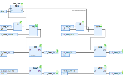
PLC Programming
Program Description
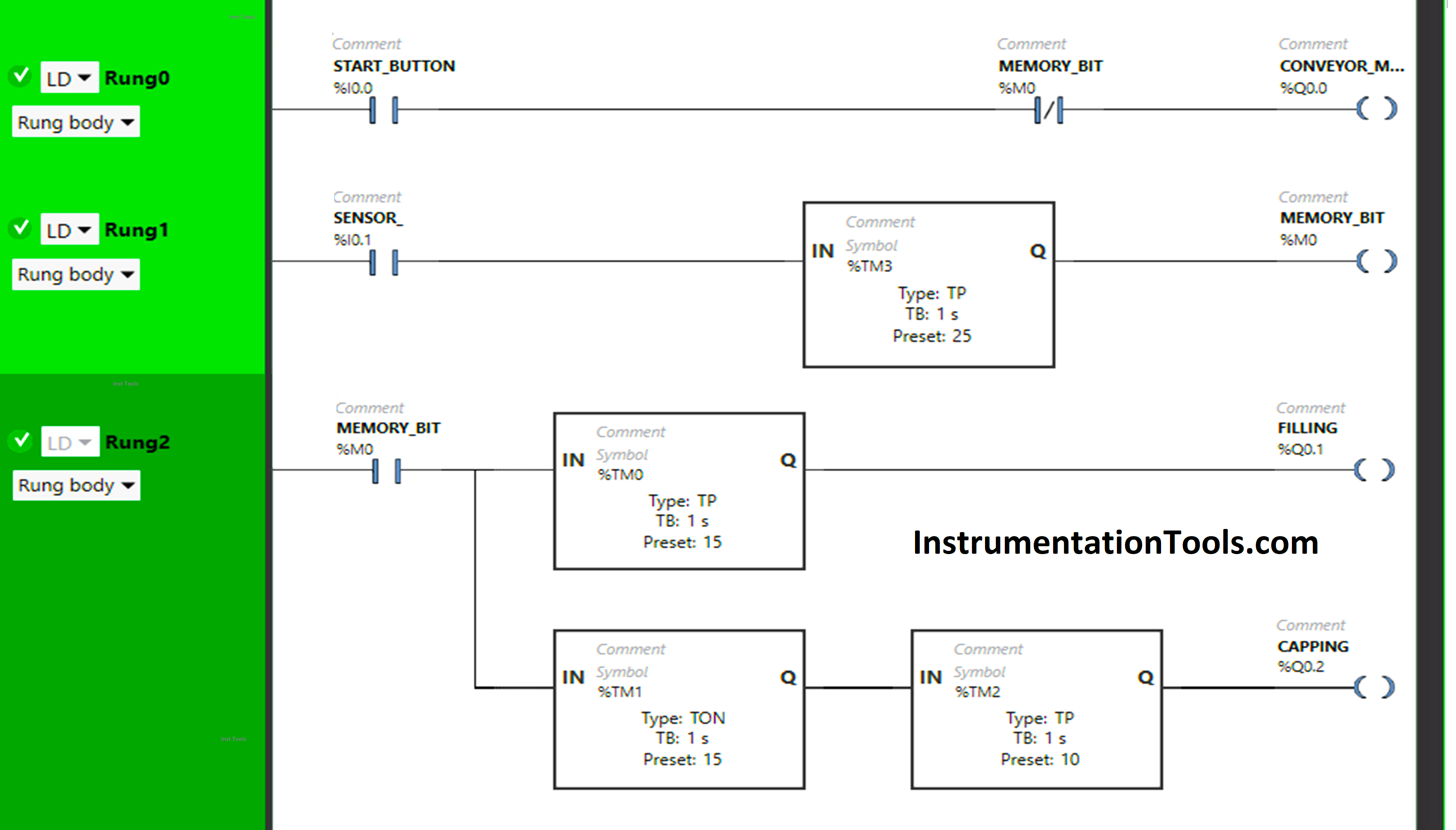
We have used Normally Open Contact for the Start Button (I0.0), Sensor (I0.1), and Memory Bit (M0).
In the above program, we have used Normally Closed Contact for Memory Bit (M0).
In Rung 0:
- Normally Open Contact is used for the Start Button (I0.0) to Turn ON the output Conveyor Motor (Q0.0).
- Normally Closed Contact is used for Memory Bit (M0) to turn OFF the output Conveyor Motor (Q0.0).
In Rung 1:
- Normally Open Contact is used for Sensor (I0.1) to Turn ON Memory Bit (M0).
- TP type timer is used to Turn ON the Memory Bit (M0) for a limited time.
In Rung 2:
- Normally Open Contact is used for Memory Bit (M0) to Turn ON the outputs Filling (Q0.1) and Capping (Q0.2).
- TP timer is used to Turn ON the output Filling (Q0.0) for a limited time.
- TON timer is used to delay the turning ON time of the output Capping (Q0.2) for some time.
- TP timer is used to Turn ON the output Capping (Q0.2) for a limited time.
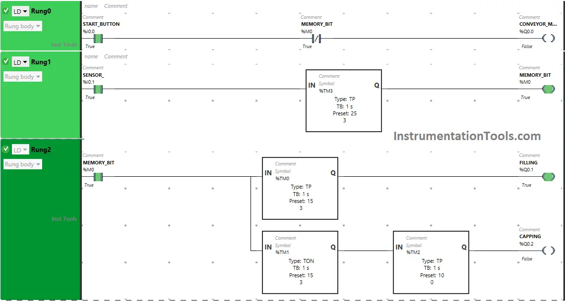
PLC Simulation Result
Let’s simulate our program and test the results. Please note that we may have shown only the required logic parts instead of the complete code.
Rung 0:
When the Start Button (I0.0) is turned ON, the output Conveyor Motor (Q0.0) turns ON as Normally Open Contact used for the Start Button (I0.0) is in True state.

In False State, Normally Closed Contact used for Memory Bit (M0) also passes the signal to turn ON the output Conveyor Motor (Q0.0)
Rung 1:
When the Sensor (I0.0) gets activated, the signal flows through it as Normally Open Contact used for Sensor (I0.0) will be in True state and Memory Bit (M0) will turn ON but for a limited time as Timer Function Block type TP is used to turn ON Memory Bit (M0) for Limited time and time is set to 25 seconds.
When Memory Bit (M0) turns ON in Rung1, it will turn ON Memory Bit in Rung0 and Rung2 also and the output Conveyor Motor (Q0.0) in Rung0 will turn OFF because Normally Closed Contact used for Memory Bit (M0) in Rung0 gets True and does not allow the signal to through it.
Rung 2:
When Memory Bit (M0) turns ON, the output Fillings (Q0.1) gets Started but for a limited time as Timer Function Block type TP is used to Turn ON the output Filling (Q0.1) for a limited time and the time set to 15 seconds. So after 15 seconds, the output Filling (Q0.1) will turn OFF.
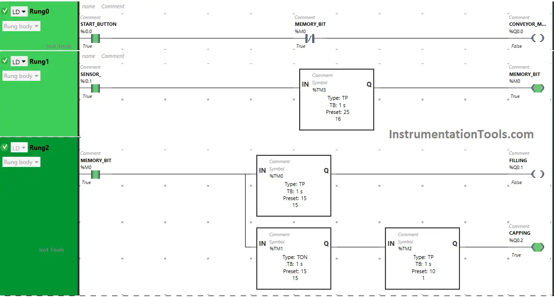
Also, when Memory Bit (M0) turns ON, the output Capping (Q0.2) will turn ON after 15 seconds (i.e immediately when the output Filling (Q0.1) turns OFF) as Timer Function Block TON is used to delay the turning ON time of the output Capping (Q0.2).
The time is set to 15 seconds. So after 15 seconds, the output capping (Q0.2) will turn ON but for a limited time as Timer Function Block type TP is used to turn ON the output Capping (Q0.2) for a limited time. The time is set to 10 seconds. So after 10 seconds, the output capping (Q0.2) will turn OFF.
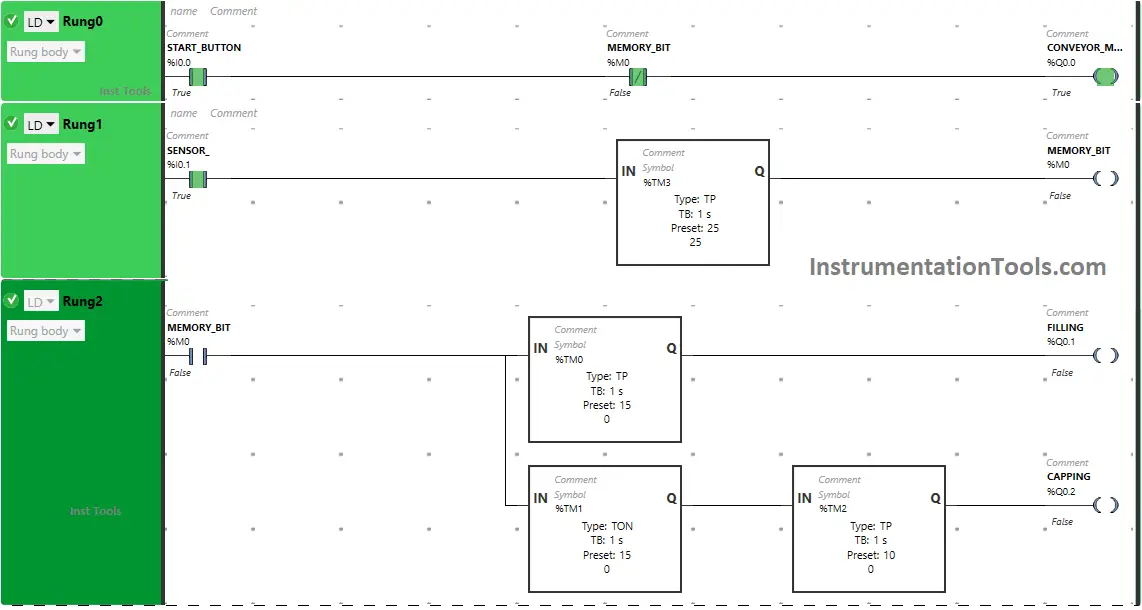
In Rung1, timer Function Block type TP reaches its set time and Memory Bit (M0) turns OFF. When Memory Bit (M0) turns OFF in Rung1, Normally Closed Contact used for Memory Bit (M0) will be in a False State and allow the signal to pass to the output Conveyor Motor (Q0.0) in Rung0 and Conveyor Motor (Q0.0) will turn ON.
If you liked this article, please subscribe to our YouTube Channel for PLC and SCADA video tutorials.
You can also follow us on Facebook and Twitter to receive daily updates.
Read Next:
- Counting Number of Bottles in Packaging
- Automatic Bottle Rejection PLC System
- Empty Bottle detection using PLC Logic
- Automatic Bottle Filling System using PLC
- Capping Machine Control System Automation