I am always surprised how an automation system like PLC or DCS does the scaling for a sensor ? or even sometimes thinking about a simple field transmitter scaling techniques for converting any type of sensor output into standard 4-20mA.
For example, consider a Temperature Transmitter and we all know by using a simple formula we can calculate the equivalent temperature from the RTD sensor output resistance And in the case of a thermocouple, a complex algorithm is required for converting its output millivolt into equivalent temperature.
So now the Question is How a PLC or DCS or Transmitter does the Scaling?
Let us discuss in detail about scaling.
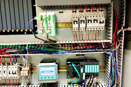
How a PLC do the Scaling for a Sensor?

Scaling is the process of taking a signal such as a process variable, voltage or current output from a sensor and applying calculations to present this signal in a more usable form in terms of engineering units, such as PSI, °F or %RH to the operator in the control room.
There are three common techniques used in the data acquisition world including linear scaling, mapped scaling and formula scaling.
All three methods have their place and time for use and will be described in this article.
Scaling Techniques
There are three techniques for scaling that we are going to cover here in this article: linear, mapping and formula.
These three techniques overlap a little bit as we will explain, but they are the primary methods used in the world of data acquisition.
Just to give a quick overview of these three methods and what they are best utilized for, we’ve put together a table below.

In certain instances where formula-based scaling is not available, mapping can sometimes be used to predefine a table based on the formula needed and vice versa.
It is also worth noting that when working with a sensor that has an analog output, the units specified for that sensor are not set in stone.
For example
if your sensor has a 4 to 20mA output for a range of -40 to 100°C, it would be just as easy to scale the output into Fahrenheit by saying that the unit has a range of -40 to 212°F. We’ll touch more on this in the next section.
Linear Scaling
The technique of linear scaling should remind you a few your days back in basic algebra. It uses the old slope-intercept form ‘y = mx + b’ where
-
y is your output (also known as engineering units value),
-
x is your input (whether it be voltages, milliamps, etc.),
-
m is your slope (also known as scale factor), and
-
b is your y-intercept (also known as offset).
As previously stated, linear scaling works best with linear voltage or current outputs in which the minimum and maximum outputs represent specific values along with the sensors range.
If you’re a bit rusty, have no fear, we’ll give you a couple of examples to freshen things up.
Example 1
Let’s consider the level Transmitter with a 0 to 100 ft WC range and 0 to 10V DC output. These specifications tell us two things:
-
An output of 0V represents a measurement of 0ftWC and
-
An output of 10V represents a measurement of 100ftWC.
It’s best to start with your scale factor, or m in the equation. The factor m can be solved by using the slope formula
m = (y2-y1) / (x2-x1)’ and choosing two points along the linear scale.
After the scale factor has been determined, we simply plug the value m back into the slope-intercept formula and use one of our points to calculate our offset.

-
We will use the two points (0, 0) and (10, 100) to calculate the scale factor or m.
m = (y2-y1) / (x2-x1) = (100 – 0) / (10 – 0) = 100 / 10
Therefore m = 10
-
Now we will use the slope-intercept formula and the point (0, 0) to calculate the offset or b.
y = mx + b, where y = 0, x = 0, m = 10, and b is unknown.
0 = 10(0) + b = 0 + b
Therefore b = 0
-
It’s always a good idea to verify that your scale factor and offset are right by plugging our second point into our completed equation, which in this case is (10, 100).
y = mx + b, where y = 100, x = 10, m = 10, and b = 0.
100 = 10(10) + 0 = 100
Given that this arithmetical operation is valid, we have verified that our scale factor and offset are correct.
Example 2
Considering that the 0 to 10V example is fairly simple, let’s move on to something more challenging like a 4 to 20mA output.
We will still use the level Transmitter with a 0 to 100ftWC range, but this time we’ll use a 4 to 20mA output. These specifications again tell us two things:
-
An output of 4mA represents a measurement of 0ftWC and
-
An output of 20mA represents a measurement of 100ftWC.
We will go about this example, in the same manner, we did the last one by first finding the scale factor and then plugging in a few numbers to calculate the offset.

-
We will use the two points (4, 0) and (20, 100) to calculate the scale factor or m.
m = (y2-y1) / (x2-x1) = (100 – 0) / (20 – 4) = 100 / 16
Therefore m = 6.25
-
Now we will use the slope-intercept formula and the point (4, 0) to calculate the offset or b.
y = mx + b, where y = 0, x = 4, m = 6.25, and b is unknown.
0 = 6.25(4) + b = 25 + b
Therefore b = -25
-
It’s always a good idea to verify that your scale factor and offset are right by plugging our second point into our completed equation, which in this case is (20, 100).
y = mx + b, where y = 100, x = 20, m = 6.25, and b = -25.
100 = 6.25(20) + (-25) = 100
Given that this arithmetical operation is valid, we have verified that our scale factor and offset are correct.
Mapped Scaling
The technique of mapped scaling often built-in and preprogrammed for inputs like thermocouples, Pt100/1000’s, and other resistive temperature sensors.
For example, when you configure your data acquisition system to measure a type K thermocouple, the system already knows what thermocouple millivolt output corresponds to what temperature.
This example does not apply only to type K thermocouples, but any type of commonly used resistive temperature sensor or other related sensors.
However, there are some instances in which we would need to create our own mapping table.
-
One of these instances would be when we are working with a data acquisition system that is not preconfigured for use with resistive temperature sensors. This is not a very common situation that we run into, but it is worth mentioning.
-
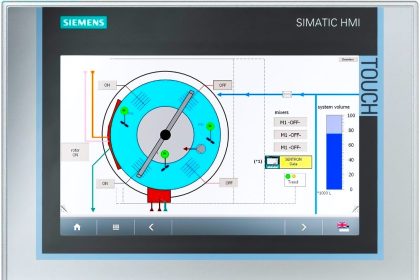
The other instance would be when we have a non-linear function and formula-based scaling is not available or is a piecewise function. A good example of this would be when we are using a level sensor to calculate tank volume in a non-linear tank.
Typically when we want to know what the volume of a fluid in a tank is we measure the depth or level of the tank.
By knowing this, we can calculate the volume of the fluid. If the tank had a flat bottom and was the same diameter along with its height then this calculation would be simple, and we could use linear scaling like above.
However, typically these tanks are rounded and the level of the fluid does not directly correlate to the volume of fluid. In this situation, we must use mapped scaling and a little bit of math to attain our desired result.

For our example we will use a horizontal cylinder tank with a diameter of 5 ft. and a length of 10 ft.
There are a number of complicated trigonometric formulas used to determine the filled volume of a tank like this that we’re going to skip over as they are too complex for the scope of this article. Instead, we will do the calculations and show you the value mapping table.
Also, for this example, we will be using the level Transmitter again, but this time a 0 to 10V DC output and 0 to 5 ft WC range.

If this is the mapping table programmed into your data acquisition system then the volume will be calculated rather than simply measuring the depth.
Typically the more points in your table the more accurate the calculations will turn out to be. To demonstrate this concept, let’s use an 1V output signal as an example.
-
An output of 1V would tell us that there is a 0.5 ft. depth in the tank. This calculates out to be approximately 76 gallons.
-
1V falls between 0V and 2V on our table, so the data acquisition system will set up a linear scale between those two points and will say that a 1V output is 104.5 gallons, which is nearly 30 gallons off!
Formula Scaling
This technique has the potential to be one of the most powerful scaling methods, however, it is often a resource hog and most data acquisition systems storing data at high rates cannot keep up with this process.
For data acquisition systems that cannot perform formula scaling there are two alternatives:
-
Storing raw values and applying the required formulas to the data after the data has been saved from the data acquisition system. This can typically be done in a piece of software such as Microsoft Excel.
-
Using a programmable signal calculator. This type of device can be configured to process multiple inputs via a user-defined formula and provide a linear output.
There are numerous potential uses for formula scaling. We will cover two possible scenarios for this technique: vertical cylinder tank volume and differential pressure.
Example 1
For a vertical cylinder tank, the fill volume can be calculated by the formula ‘V = π r2 f ‘ where
-
V is the volume filled,
-
r is the radius of the tank, and
-
f is the fill height.
Let’s say that our tank has a diameter of 5 ft. and a height of 10 ft. Again, let’s use the level Transmitter for our example with a 0 to 10 ft WC range and 0 to 5V DC output.
The level Transmitter is giving us our fill height or f. From this fill height, we can directly calculate the fill volume or V. We will be using some of the same methods for linear scaling to get our f and applying the calculations on top of that.
-
We will first calculate the linear scaling for the fill height or f. I’m going to skip a few steps since we covered this in the first section.
y = f = 2x, where x is the voltage output of the sensor.
-
Now we can replace the f in the vertical cylinder tank formula with 2x.
V = π r2 f = π (2.5)2 (2x) = π 12.5x
Example 2
The second scenario that we are going to use to explain the technique of formula scaling is differential pressure.
There are obviously a number of differential pressure sensors out there that give a linear output, but from experience, I can tell you that there is are a lot of uses for this method of calculating differential pressure.
In this example, we will use two of the transmitters with a 0 to 100 PSI range and 0 to 10 V DC output.
One will be placed inside a pressurized vessel submerged below water and the other will be placed outside of this vessel. The differential pressure will determine the amount of force that is being exerted on the walls of the vessel.
The calculations here are very simple. Simply subtract one from the other.
Pdifferential = Pexternal – Pinternal
Conclusion
There three most commonly used techniques for scaling sensor outputs are
- Linear scaling,
- Mapped scaling and
- Formula scaling.
As you can see, there are many instances in which more than one of these techniques can work and the best choice usually depends on the hardware/software that you’re working with.
Linear scaling is the easiest to work with, however, sensors with linear outputs tend to be more expensive as additional hardware is required to linearize the raw output from the transducer.
Mapped scaling is used more often than we tend to even notice. Any time a resistive temperature sensor is giving you a temperature reading, mapped scaling is at work somewhere along the line.
Formula scaling is very powerful but requires hardware/software configurations.
Article Source: Omni Instruments


Wonderful. Very Informative & i am very happy to learn the basics. Good Site.
Very helpful. I didn’t have an idea about all this. You are the man.
Nice information . It will be very use full to me.
You are doing great service to humanity; more grease to your elbows .I want to become an automation expert in the future.
First I wanna say You Thank you .. for sharing your experience to us.
This Site is very useful to new generation to grow up their knowledge.
I see most comments were posted a while ago but today i am posting to confirm that even today this site is very helpful as a refresher and to teach new things. Please do not stop passing your knowledge to us the younger generation
Good
You are doing a great job thank you so much
Hii I want to