In general, a steam trap consists of a valve and a device or arrangement that causes the valve to open and close as necessary to drain the condensate from piping without allowing the escape of steam. Steam traps are installed at low points in the system or machinery to be drained.
Impulse Steam Trap
Impulse steam traps, illustrated in Figure, pass steam and condensate through a strainer before entering the trap. A circular baffle keeps the entering steam and condensate from impinging on the cylinder or on the disk. The impulse type of steam trap is dependent on the principle that hot water under pressure tends to flash into steam when the pressure is reduced.
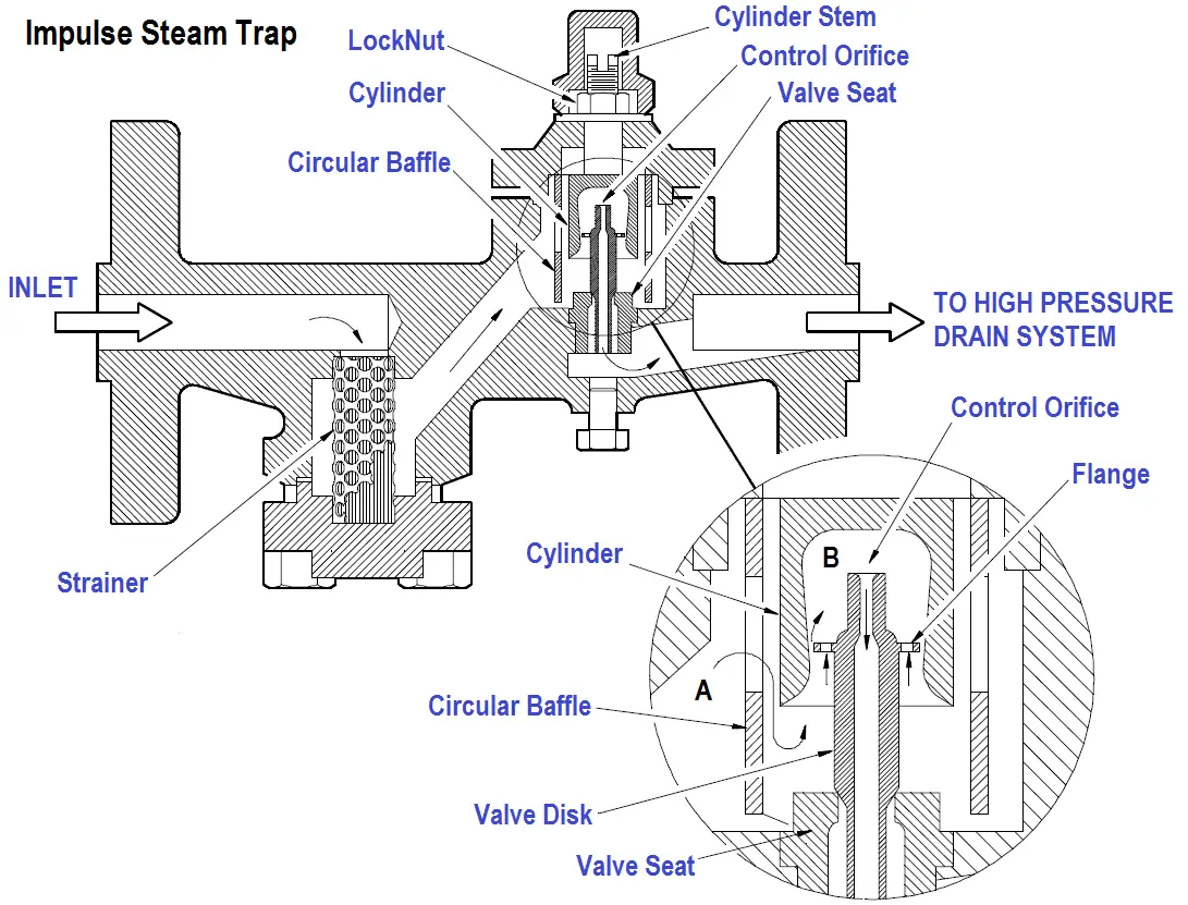
Figure : Impulse Steam Trap
The only moving part in the steam trap is the disk. A flange near the top of the disk acts as a piston. As demonstrated in Figure, the working surface above the flange is larger than the working surface below the flange.
A control orifice runs through the disk from top to bottom, which is considerably smaller at the top than at the bottom. The bottom part of the disk extends through and beyond the orifice in the seat. The upper part of the disk (including the flange) is inside a cylinder. The cylinder tapers inward, so the amount of clearance between the flange and the cylinder varies according to the position of the valve. When the valve is open, the clearance is greater than when the valve is closed.
When the trap is first placed in service, pressure from the inlet (chamber A) acts against the underside of the flange and lifts the disk off the valve seat. Condensate is thus allowed to pass out through the orifice in the seat; and, at the same time, a small amount of condensate (called control flow) flows up past the flange and into chamber B. The control flow discharges through the control orifice, into the outlet side of the trap, and the pressure in chamber B remains lower than the pressure in chamber A.
As the line warms up, the temperature of the condensate flowing through the trap increases. The reverse taper of the cylinder varies the amount of flow around the flange until a balanced position is reached in which the total force exerted above the flange is equal to the total force exerted below the flange. It is important to note that there is still a pressure difference between chamber A and chamber B. The force is equalized because the effective area above the flange is larger than the effective area below the flange. The difference in working area is such that the valve maintains at an open, balanced, position when the pressure in chamber B is approximately 86% of the pressure in chamber A.
As the temperature of the condensate approaches its boiling point, some of the control flow going to chamber B flashes into steam as it enters the low pressure area. Because the steam has a much greater volume than the water from which it is generated, pressure builds up in the space above the flange (chamber B). When the pressure in this space is 86% of the inlet pressure (chamber A), the force exerted on the top of the flange pushes the entire disk downward and closes the valve. With the valve closed, the only flow through the trap is past the flange and through the control orifice. When the temperature of the condensate entering the trap drops slightly, condensate enters chamber B without flashing into steam. Pressure in chamber B is thus reduced to the point where the valve opens and allows condensate to flow through the orifice in the valve seat. The cycle is repeated continuously.
With a normal condensate load, the valve opens and closes at frequent intervals, discharging a small amount of condensate at each opening. With a heavy condensate load, the valve remains open and allows a continuous discharge of condensate.