In industrial instrumentation and control systems, the 4-20 mA current loop is one of the most widely used methods for transmitting analog signals over long distances. This simple yet highly effective standard is commonly used for sensors and transmitters to communicate real-world process variables like pressure, temperature, flow, and level.
To interpret this current and convert it into meaningful engineering units (e.g., liters, degrees Celsius, PSI), a conversion is required. This is where our 4–20 mA to Measurement Converter Tool comes in.
Objective of the Tool
The main goal of this tool is to provide a quick and accurate way to convert a 4–20 mA signal to its corresponding linear measurement value. It helps technicians, engineers, and students understand signal scaling, verify instrument outputs, and test sensor ranges.
4–20 mA to Measurement Converter
Key Terms
- mA (milliamps): The current signal, typically ranging from 4 mA (minimum) to 20 mA (maximum).
- Engineering Value / Process Variable: The actual quantity being measured, such as temperature, pressure, or flow rate (measurement range: min and max).
- Span: The difference between the maximum and minimum measurement values.
- Linear Scaling: A straight-line relationship between the mA signal and the measurement value.
4-20 mA to Measurement Conversion Formula
To convert a 4–20 mA signal into a linear measurement value, the following formula is used:
Measurement = Min + ((mA – 4) / 16) * (Max – Min)
Formula
Where:
- mA = 4-20 mA Current input
- Min = Minimum measurement value (corresponding to 4 mA)
- Max = Maximum measurement value (corresponding to 20 mA)
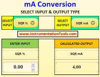
How to Use the Tool?
- Input Current (mA): Enter the measured or simulated current from the sensor (between 4.00 and 20.00 mA).
- Minimum Value: Enter the corresponding engineering unit for 4 mA (e.g., 0 °C, 0 LPM).
- Maximum Value: Enter the corresponding value for 20 mA (e.g., 100 °C, 500 LPM).
- Click Convert: The tool will instantly display the scaled measurement result.
Example Calculation
Let’s assume:
- Input Current = 12 mA
- Min Value = 0
- Max Value = 100
Apply the formula:
Measurement = 0 + ((12 - 4) / 16) * (100 - 0)
            = (8 / 16) * 100
            = 0.5 * 100
            = 50
So, 12 mA corresponds to 50 units in the measurement scale.
10 Detailed Practical Questions and Solutions
This section comprises 10 practical questions related to converting 4-20 mA signals to the respective process measurements.
- Pressure Transmitter (0–10 bar)
- Temperature Sensor (0–200 °C)
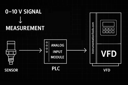
- PLC Analog Input: Level Transmitter Scaling
- PLC Flow Signal Scaling
- Control Valve Position Feedback
- pH Transmitter (2–12 pH)
- Speed Sensor (500–3000 RPM)
- Conductivity Transmitter (0–1000 µS/cm)
- Distance Sensor (10–100 cm)
- Tank Level Transmitter (500–1500 mm)
- Weight Sensor (0–200 kg)
Pressure Transmitter (0–10 bar)
Question: A pressure transmitter is calibrated from 0 to 10 bar and outputs a 4–20 mA signal. If the current measured by the PLC is 8 mA, what is the pressure reading?
Solution:
Measurement = 0 + ((8 – 4) / 16) * (10 – 0) = (4 / 16) * 10 = 0.25 * 10 = 2.5 bar
Temperature Sensor (0–200 °C)
Question: A PT100 temperature sensor with transmitter outputs 4–20 mA for 0 to 200 °C range. If the signal reads 16 mA, calculate the temperature.
Answer:
Measurement = 0 + ((16 – 4) / 16) * 200 = (12 / 16) * 200 = 0.75 * 200 = 150 °C
PLC Analog Input: Level Transmitter Scaling
Question: A PLC receives a 13.6 mA current signal from a level transmitter configured for a 0–5 meter tank. What is the tank level?
Answer:
Level = 0 + ((13.6 – 4) / 16) * (5 – 0)
Level = (9.6 / 16) * 5
Level = 0.6 * 5
Level = 3.00 meters
PLC Flow Signal Scaling
Question: A flow transmitter sends 6.4 mA to a PLC analog input module. The transmitter range is 0 to 1000 LPM. What is the actual flow?
Answer:
Flow = 0 + ((6.4 – 4) / 16) * (1000 – 0)
Flow = (2.4 / 16) * 1000
Flow = 0.15 * 1000
Flow = 150 LPM
Control Valve Position Feedback
Question: A PLC receives a 15.2 mA feedback signal from a control valve’s position transmitter. The transmitter is configured such that 4 mA corresponds to 0% open and 20 mA to 100% open. What is the actual valve opening percentage?
Answer:
Valve Opening (%) = 0 + ((15.2 – 4) / 16) * 100
Valve Opening (%) = (11.2 / 16) * 100
Valve Opening (%) = 0.7 * 100
Valve Opening = 70.00%
pH Transmitter (2–12 pH)
Question: A pH transmitter outputs a signal from 2 to 12 pH across 4–20 mA. At 18 mA, what is the measured pH value?
Answer:
Measurement = 2 + ((18 – 4) / 16) * (12 – 2) = (14 / 16) * 10 = 0.875 * 10 = 8.75 pH
Speed Sensor (500–3000 RPM)
Question: A speed sensor is calibrated from 500 to 3000 RPM and connected to a PLC. If the measured current is 6 mA, what RPM does this indicate?
Answer:
Measurement = 500 + ((6 – 4) / 16) * (3000 – 500) = (2 / 16) * 2500 = 0.125 * 2500 = 812.5 RPM
Conductivity Transmitter (0–1000 µS/cm)
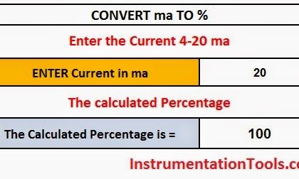
Question: A conductivity transmitter outputs 20 mA at full scale (1000 µS/cm). What is the conductivity at 20 mA?
Answer:
Measurement = 0 + ((20 – 4) / 16) * 1000 = 1 * 1000 = 1000 µS/cm
Distance Sensor (10–100 cm)
Question: A distance sensor is configured to measure from 10 to 100 cm. What is the detected distance at 11 mA?
Answer:
Measurement = 10 + ((11 – 4) / 16) * (100 – 10) = (7 / 16) * 90 = 0.4375 * 90 = 49.375 cm
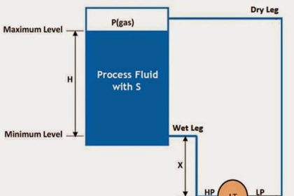
Tank Level Transmitter (500–1500 mm)
Question: A tank level transmitter is set from 500 mm to 1500 mm. If the signal is 15 mA, calculate the level.
Answer:
Measurement = 500 + ((15 – 4) / 16) * (1500 – 500) = (11 / 16) * 1000 = 0.6875 * 1000 = 1187.5 mm
Weight Sensor (0–200 kg)
Question: A load cell sends a signal from 4 to 20 mA representing 0–200 kg. What is the weight reading when current is 14 mA?
Answer:
Measurement = 0 + ((14 – 4) / 16) * 200 = (10 / 16) * 200 = 0.625 * 200 = 125 kg
Use Cases
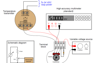
- Field Calibration: Technicians use this tool to verify transmitter outputs during loop checks.
- PLC/SCADA Scaling Verification: Engineers cross-check logic and scaling parameters.
- Educational Demonstrations: Trainers and students use this tool to understand how current loops map to physical quantities.
- Simulation and Testing: Used in labs and development for hardware simulation.
Advantages of Using the Tool
- No installation needed; works in browser
- Instant, accurate results
- Supports any custom range
- Mobile-friendly and easy to use on-site
Conclusion
The 4–20 mA to Measurement Converter Tool simplifies a fundamental concept in instrumentation. For verifying process signals or when a student learns the basics of analog signal scaling, this tool offers a practical and efficient solution.
Try it out in your daily workflow and experience the convenience of fast, accurate analog-to-engineering conversions!