Inst ToolsInst ToolsInst Tools
  • Courses
  • Automation
    • PLC
    • Control System
    • Safety System
    • Communication
    • Fire & Gas System
  • Instrumentation
    • Design
    • Pressure
    • Temperature
    • Flow
    • Level
    • Vibration
    • Analyzer
    • Control Valve
    • Switch
    • Calibration
    • Erection & Commissioning
  • Interview
    • Instrumentation
    • Electrical
    • Electronics
    • Practical
  • Q&A
    • Instrumentation
    • Control System
    • Electrical
    • Electronics
    • Analog Electronics
    • Digital Electronics
    • Power Electronics
    • Microprocessor
  • Request
Search
  • Books
  • Software
  • Projects
  • Process
  • Tools
  • Basics
  • Formula
  • Power Plant
  • Root Cause Analysis
  • Electrical Basics
  • Animation
  • Standards
  • 4-20 mA Course
  • Siemens PLC Course
Reading: Interface Level Measurement using DP Transmitter
Share
Notification Show More
Font ResizerAa
Inst ToolsInst Tools
Font ResizerAa
  • Courses
  • Design
  • PLC
  • Interview
  • Control System
Search
  • Courses
  • Automation
    • PLC
    • Control System
    • Safety System
    • Communication
    • Fire & Gas System
  • Instrumentation
    • Design
    • Pressure
    • Temperature
    • Flow
    • Level
    • Vibration
    • Analyzer
    • Control Valve
    • Switch
    • Calibration
    • Erection & Commissioning
  • Interview
    • Instrumentation
    • Electrical
    • Electronics
    • Practical
  • Q&A
    • Instrumentation
    • Control System
    • Electrical
    • Electronics
    • Analog Electronics
    • Digital Electronics
    • Power Electronics
    • Microprocessor
  • Request
Follow US
All rights reserved. Reproduction in whole or in part without written permission is prohibited.
Inst Tools > Blog > Instrumentation Tools > Interface Level Measurement using DP Transmitter

Interface Level Measurement using DP Transmitter

Last updated: November 12, 2019 4:33 pm
Editorial Staff
Instrumentation Tools Level Measurement
13 Comments
Share
6 Min Read
SHARE

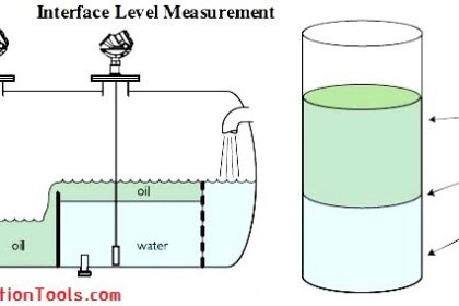
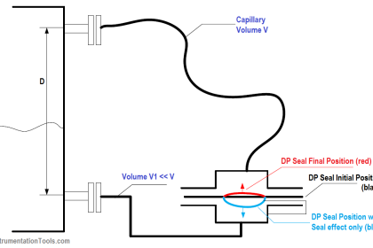
Differential pressure (DP) transmitters are used to measure the interface of two fluids that have different specific gravities (S1 & S2). To make an interface measurement, the overall level must be at or above the low pressure tap at all times. It is important that the level be large enough to create a reasonable DP between the two specific gravity extremes. This measurement can be done with or without remote seals.

However, from a maintenance point of view, it may be easier to use a remote seal assembly; keeping the wet leg at a constant height can be difficult in some applications.

To determine the calibrated range for the transmitter, four assumptions need to be made:

  1. At the lower calibrated value, 4 mA point, the tank is filled with the lighter fluid.
  2. At the upper calibrated value, 20 mA point, the tank is filled with the heavier fluid.
  3. The taps leading to the transmitter are flooded at all times. The overall level should be equal to or higher than the upper (low pressure) tap.
  4. There is always a reference level seen by the low pressure side. This can be accomplished with either a remote seal system or a wet leg. The reference level must have a constant height and density. The calculation is modified slightly for wet leg systems when the density of the high and low pressure wet legs differ.

The measured level is composed of a combination of the two fluids:

L = L1S1 + L2S2

When the tank is filled with the lighter fluid, the transmitter will be at 4 mA (or 0% of span) and L2 = L:

HP = L2S2 + dSf

LP = dSf + hSf

At 4 mA, DP = HP – LP = L2S2 – hSf

When the tank is filled with the heavier fluid, the transmitter will be at 20 mA (or 100% of span) and L1 = L:

HP = L1S1 + dSf

LP = dSf + hSf

At 20 mA, DP = HP – LP = LS1 – hSf

Interface Level Measurement

Interface Level Measurement using DP Transmitter
Calculation for interface measurement
This tool is used to calculate the DP transmitter ranges for interface measurement application

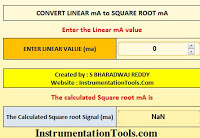
The formulas used to calculate calibration ranges of a DP transmitter for interface measurement application

 The Transmitter 4ma or LRV formula
 ∆Pmin or 4ma =  LS2 – HSf
The Transmitter 20ma or URV formula

∆Pmax or 20ma = LS1 – HSf

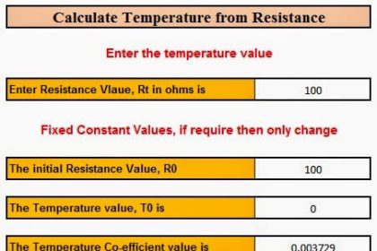
Using the above tools, we are calculated the transmitter ranges. Now calibrate the transmitter and take into line. Now note down the present DP value of transmitter for calculating the interface level.

Now enter the Span, L and LRV of transmitter in DP scale (Transmitter 4ma value in DP scale) parameters which can obtained from above interface measurement transmitter calibration tool. As we taken transmitter into line, the measured DP can be obtained. Now substitute all the parameters in the below interface calculation tool. 

The formula used to calculate interface level using DP transmitter for interface measurement application are:
Formula for interface level measurement
Where,
H = Distance between taps
L = Total Measured Level
S1 = Specific gravity of lighter fluid
S2 = Specific gravity of heavier fluid
Sf = Specific gravity of reference leg
Measured DP= After transmitter calibration, present DP value
Span = Difference between absolute of maximum and minimum range
LRV = Lower range value of transmitter in DP scale
I = Interface level

Interface Measurement using DP Transmitters

Advantages

  • Low cost
  • Simple to install
  • No additional components required

Limitations

  • Span must be sufficiently large enough to measure; either the distance between taps or the specific grabity difference m7ust be large
  • Upper tap must be covered at all times.
  • Small spans are susceptible to temperature induced errors.

Example Problem:

A vessel requires an interface measurement where the level is 150 inches. The vessel has two fluids with specific gravities of 1.0 and 1.08.

DP Transmitter Interface Level Measure

At 4mA, DP = L2S2 – hSf

DP = (150 x 1.0) – (150 x 0.934)

So at 4 mA = 9.9 inH2O DP

At 20mA, DP =  LS1 – hSf

DP = (150 x 1.08) – (150 x 0.934)

So at 20 mA = 21.9 inH2O DP

The calibrated span is 9.9 to 21.9 inH20. When the transmitter reads 9.9 inH20, the tank is filled with the lighter fluid. When the transmitter reads 21.9 inH20, the tank is filled with the heavier fluid.

To determine where the interface of a mixture of fluids is, use the DP reading as a percent of span. For example, if the transmitter output is 18.4 mA or a DP of 20.7 inH2O, the interface is calculated by using the formula:

Interface Level Calculation Formula using DP Transmitter

Don't Miss Our Updates
Be the first to get exclusive content straight to your email.
We promise not to spam you. You can unsubscribe at any time.
Invalid email address
You've successfully subscribed !

Continue Reading

What is a Submersible Pressure Transmitter? Principle, Advantages
Calculate Current (4-20ma) from Process variable PV
DP Level Transmitter Elevation and Suppression Corrections
Closed tank Density Measurement using DP Transmitter with dry leg & constant level application
What is a Level Switch? Types of Level Switches
Density Measurement for Open Tank with Constant Level Application
Share This Article
Facebook Whatsapp Whatsapp LinkedIn Copy Link
Share
13 Comments
  • Karthik vamula says:
    April 22, 2015 at 3:49 pm

    Really helped me…Sharing is good.

    Reply
  • Vardhan says:
    April 23, 2015 at 4:45 am

    Hi,

    Can you please share interface level measurement using radar.

    Reply
    • S Bharadwaj Reddy says:
      April 23, 2015 at 7:28 am

      Hi, Vardhan,

      Interface level measurement using radar tool will be posted soon.

      Thanks,
      S Bharadwaj Reddy

      Reply
  • Chitramani says:
    May 29, 2015 at 4:38 pm

    Mind Blowing tools dude. Thanks for sharing these applications.

    Reply
  • soulfly says:
    August 2, 2015 at 8:58 am

    Could you please explain,how to calculate the range if the transmitter is installed above the HP side
    thanks n advance

    Sajeesh sathyapalan

    Reply
  • ritesh patel says:
    March 17, 2016 at 3:54 pm

    why you are not using d value in calculation

    Reply
    • S Bharadwaj Reddy says:
      March 18, 2016 at 4:30 am

      Hello Ritesh, The Post is updated with detail information. Thanks for the query.

      Reply
  • zalielt says:
    May 10, 2016 at 5:57 am

    Regarding remote seal or wet leg, assumption no. 4 said the tube must always be filled with the liquid and the liquid should has constant density. I’m confuse, if the tube always be filled with known liquid, means that at the LP side, the pressure is constant even though no liquid in the tank, because of the liquid in the tube?

    Reply
  • S Bharadwaj Reddy says:
    May 10, 2016 at 9:11 am

    Hello, Yes, Even though there was no level in the tank, the Wet leg or LP side always pressure will be there and in negative number. In calibration or range calculation we compensate this extra pressure. Click Here to read the article.

    Reply
  • Imran says:
    September 11, 2016 at 5:44 am

    There is an text error in your formula calculator, please change it , S2 is lighter fluid but typed heaver fluid with it in calculator.

    Reply
  • Chirag Jadav says:
    July 10, 2018 at 12:34 pm

    Dear sir,
    thanks for the sharing, I have one doubt regarding to interface level formula that Can u please explain in detail that how this formula came? then it will be very helpful for us.

    Reply
  • prakash yadav says:
    November 27, 2018 at 11:53 pm

    For non interface the leg in the HP side allows the process liquid, but in interface type, both legs are filled with same leg liquid, am I right ? Plz make my doubt clear.

    Reply
  • bosco says:
    November 30, 2018 at 11:04 am

    your calculations did not include the height d.

    for eg, at 4 mA it’s supposed to be (L2S2 + dSf) – (d+h)Sf, right?

    Reply

Leave a Reply Cancel reply

Your email address will not be published. Required fields are marked *

Stay Connected

128.3kFollowersLike
69.1kFollowersFollow
210kSubscribersSubscribe
38kFollowersFollow

Categories

Explore More

Differential Pressure (DP) Level transmitter Installed Below Tapping Point
Rotary Level Switch Working principle Animation
Bubbler Level Sensor
Float & Dial Level Gauge Principle
Displacer Interface Level Measurement
Advantages & Disadvantages of Level Measurement Systems
What is a Bridle?
Closed tank DP Level Transmitter with wet leg elevation zero direct mount Calibration

Keep Learning

Slop Tank Level Transmitter Erection

Wrong Installation of Horn Type Radar Level Transmitter on Sloping Tank

Servo Operated Float Level Measurement

Servo Operated Float Level Measurement

Weight-based Level Instruments Principle

Weight-based Level Measurement Principle

radar-level-sensor-

Non-Contacting Radar Level Transmitter Working Principle

Closed Tank DP Level Transmitter

How to Find LRV and URV of Closed Tank DP Level Transmitter

Closed-tank-DP-Level-Transmitter-with-cleaning-leg-Calibration

Closed tank DP Level Transmitter with cleaning leg Calibration

Micro-impulse Level Transmitter Principle

Micro-impulse Level Transmitter Principle

Magnatic Level Indicators Working Animation

Magnetic Level Indicators Working Animation

Learn More

Open User Communication in Siemens Tia Portal - PLC to PLC

Open User Communication in Siemens Tia Portal – PLC to PLC

Block Diagram

Block Diagram

Electrodynamometer Movement Principle

Electro-Dynamo Meter Movement

sinking-and-sourcing-digital-output-modules

PLC Digital Signals Wiring Techniques

Mass Spectrometer Questions and Answers

Tandem Mass Spectroscopy

Pneumatic and Hydraulic Projects

200 Pneumatic and Hydraulic Projects List

What is Profibus

All About Fieldbus Protocols

Difference between SR Flipflop and RS Flipflop

Difference between SR Flipflop and RS Flipflop ?

Menu

  • About
  • Privacy Policy
  • Copyright

Quick Links

  • Learn PLC
  • Helping Hand
  • Part Time Job

YouTube Subscribe

Follow US
All rights reserved. Reproduction in whole or in part without written permission is prohibited.
Welcome Back!

Sign in to your account

Username or Email Address
Password

Lost your password?