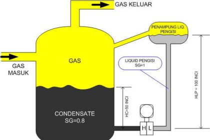
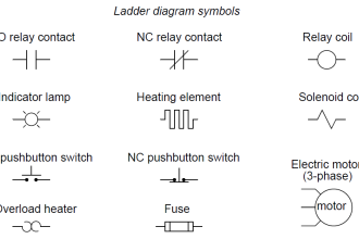
DP Level Transmitter Calculation for Diaphragm seal type with capillary tube
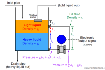
For determining the DP level transmitter calibration range for this type, we need fill fluid density inside the capillary tube, Process fluid density, Distance between HP & LP tapping points, Maximum level to be measured.
Sometimes the distance between HP & LP tapping points and Maximum level to be measured are same or may be different and entirely depends on your application, transmitter installations or process requirement.
If the transmitter capillary tube is filled with same fill fluid then no need to consider transmitter mounting elevation. The transmitter mounting elevation must be considered when one diaphragm is connected and other diaphragm opened to atmosphere. Here in this example we considered same fill fluid in capillary tube and both diaphragms are connected to the tank.
Capillary Seal Differential Pressure Level Transmitter
 |
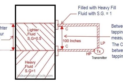
| DP Level Transmitter Calibration for Diaphragm Seal with capillary tube type |
The formulas for calculating transmitter URV and LRV are as follows:
HP Side or LRV or Transmitter 0% = – ρF . g .H2
LP Side or URV or Transmitter 100% = (ρP . g . H1) – (ρF . g . H2)
Where
H1 = Maximum level to be measured
H2 = Height difference between HP & LP tapping points
ρP = Process fluid density in the tank
ρF = Fill fluid density inside the capillary tube
g = Gravitational acceleration
Note:
1.In this example the tank maximum level (100%) to be measured (H1) is considered below the LP tapping point height (H2).
2.In some cases maximum level to be measured and LP tapping point height may be same. Hence enter Height difference between HP & LP tapping points value in H1 & H2
The Following tables specifies the fill fluid constant values:


OMG……I am calibrated my transmitter now….Working Fine.Thanks for sharing.
I have tank with size 72 inches between HP to LP ?
What will be URV and LRV ?
Transmitter is mounted above the tapping points
This site was… how do I say it? Good!! Finally I have found something which helped me. Cheers!|
How to calibrate capillary type interface level transmitter
looks like a good tool to have, If it worked!!!!
is the level in meter or mm??
please help to calculate
HI in = 450 mm
H2 = 500 in mm\
sg of fill fluid = 1.3 flourine
sg of pro fluid = 1.1 amine
please calculate i need to calculate cappilary transmitter
Are The H1 and H2 values in meters or feet?
Dear Bhardwaj,
the values of H1 and H2 in mm or meter.
Thanks for this very useful article
For vacuum applications fill fluid silicon 200 has given best results
Capillary transmitter giving increasing mA with decreasing level
What is fault?
Do you offer any courses
Not Yet. I am planning for a short course this year.
how this range comes in mbar, if we are taking level in mm the it should be comes in mmh20 ?
Hi,
Simply by conversion : 1mmH2O = 0.09806648572 mbar.
what are the units?
What happed the level calibration tool ? It was very helpful when someone in a hurry to figure level calibration.
What if my Level Transmitter is mounted between HP leg & LP leg? Does this same calculation works to calibrate level transmitter?