One of the most used panels with a PLC panel is an MCC panel. In large-scale industrial automation systems, there are an equal number of motors and all of their control is not fitted in a single panel.
In fact, there are multiple distributed small panels in a single cabinet for controlling their operations. This is nothing but an MCC or motor control center panel. PLC panels need to be designed and interfaced accordingly for proper communication of control signals between them.
In this post, we will explain how to properly interface PLC and MCC panels with each other.
What is a PLC Panel?
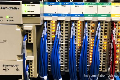
A PLC panel is a control panel that houses a PLC. PLC consists of components like a 3-phase power supply switch, circuit breakers, relays, transformer, line choke filters, PLC, SMPS, earthing points, and terminal boards.
It is basically defined as control of the PLC operation by interfacing the outside wiring of the field devices inside it and controlling it through the logic written in the CPU. It is not intended to house high-frequency electrical components or large-scale current rating devices as the PLC is low-power and it can damage the internal circuitry through short circuits or create electromagnetic noise in the panel which disturbs sensitive PLC signal operation.
What is an MCC Panel?
An MCC panel is a motor control panel that houses heavy electrical components for controlling the operation of a motor. MCC has components like a busbar, three-phase switch, relays, terminal boards, contactors, thermal overload relays, soft-starters, VFD, or other types of starters.
As discussed earlier, these cannot be inserted inside a PLC panel as they have a large current flow and can interfere with low-frequency signals of PLC control components.
It is designed to simplify the wiring of a motor by not mixing it inside the PLC panel. It is used when the motor is desired to be run in both the local and remote modes.
Remote mode means the motor will be controlled through PLC and local mode means the motor will be controlled by pressing local start and stop buttons on the MCC panel door.
So, if there are 10 motors in an application, it helps to distribute the load properly and also avoids any complexity in wiring. Troubleshooting becomes easier through this.
Interfacing Signals of PLC and MCC Panels
Refer to the below image. It is the most basic idea of how a PLC and MCC panel interfaces.
The aim is to take inputs from the MCC panel to the PLC panel and give outputs from the PLC panel to the MCC panel. This is because the motor will give feedback to the PLC and the PLC will in turn control its operation.
The most used types of control wiring between these two panels are:
Start command
The Start command will be a momentary pulse-type output from the PLC relay to the MCC relay for latching it in remote mode and starting the motor.
Stop command
The Stop command will be a momentary pulse-type output from the PLC relay to the MCC relay for unlatching it in remote mode and stopping the motor.
Run feedback
The Run feedback is a signal from the MCC relay to PLC input for indicating to the PLC whether the motor is running or not. The feedback will be taken from any auxiliary contact inside the MCC relay or a VFD / soft starter if used.
Trip feedback
The Trip feedback is a signal from the MCC relay to PLC input for indicating to the PLC whether the motor has tripped or not. The feedback will be taken from any auxiliary contact inside the MCC relay or a VFD / soft starter if used.
Local remote feedback
The Local remote feedback is a signal from the MCC relay to PLC input for indicating to the PLC whether the motor is to be operated in local mode or remote mode. The feedback will be taken from any auxiliary contact of the switch placed outside for operation.
Emergency Switch feedback
The Emergency Switch feedback is a signal from the MCC relay to PLC input for indicating to the PLC whether the emergency stop for the motor has been pressed or not. The feedback will be taken from any auxiliary contact of the switch placed outside for operation.
Control Switch feedback
The Control Switch feedback is a signal from the MCC relay to the PLC input for indicating to the PLC whether the control power supply for that panel is on or off. The feedback will be taken from any auxiliary contact of the switch placed outside for operation.
The control power is used for powering the internal control circuits. It is the same as the circuit breaker inside a panel for turning it on or off. Without control power, none of the components of the 230V AC supply inside will get power and in short, they cannot operate in either local or remote modes.
Motor speed feedback
The Motor speed feedback is an analog signal feedback from VFD / soft starter to PLC input for indicating the current speed of the motor.
Motor speed control
The Motor speed control is analog signal feedback from PLC to VFD input for controlling the speed of the motor.
Some important points to remember here are:
If input is to be given to PLC, then the common must be taken from the PLC panel to complete the path. If the input is to be given to the MCC box, then the common must be taken from the MCC box cabinet to complete the path. Any wrong potential supply given in common terminals can create chances of short-circuit.
If a communication cable is used between the PLC and MCC panel, then proper earthing and shielding must be ensured and also, these cables should not run from near the power cables to reduce or eliminate noise effect.
Many times, local interlocking is done in the MCC panel control wiring to stop the motor in case of a trip or other abnormalities in such a way that it cannot be even operated from a remote position. Such interlocks must be properly studied by PLC engineers before designing the interface.
If you liked this article, then please subscribe to our YouTube Channel for Instrumentation, Electrical, PLC, and SCADA video tutorials.
You can also follow us on Facebook and Twitter to receive daily updates.
Read Next:
- What is Smart or Intelligent MCC?
- Motor Control Center Advantages
- Troubleshooting Automation Systems
- Distributed Control System Philosophy
- Immersion Electrical Heaters Wiring Circuits