In this article, we will discuss about the electrical drawings and types of electrical diagrams mostly used in the industrial sectors.
Electrical Drawings
In today’s world, we use drawing to convey information about a piece of equipment in a form that all those involved in its production, installation, and service will understand.
Drawing is also one of the tools for communication for sharing the information or knowledge or views of one person with another in a graphical form to get the job done in the manufacturing or production field.
An electrical drawing is a type where the connection between the electrical equipment and devices will be denoted for the action of machinery and their maintenance activities. This electrical drawing mainly constitutes the electrical devices and their connections only.
The different types of electrical drawings are:
- Circuit Diagram
- Wiring Diagram
- Wiring Schedule
- Block Diagram
- Parts List (Bill of Materials)
- Single Line Diagram (for 3 Phase)
Circuit Diagram
Circuit Diagrams show how the electrical components are connected together and use the symbol to represent the electrical components. Lines represent the functional conductors or wires which connect them together.
A circuit diagram is derived from a block or functional diagram. It does not show the exact shape, size, or layout of the electrical components. Although you could wire up an assembly from the information given in it. They usually show the detail of how an electrical circuit works.
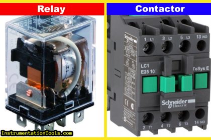
For Example, below is the circuit diagram of a simple DOL (Direct on Line) starter which is used for starting the motor. It consists of components like Circuit Breaker, Contactor, an Overload relay in the power circuit, and Start & stop push buttons and a contactor coil in the control circuit. They are not the real components but their symbols.
An electrical circuit diagram mostly uses the symbol of the components for the connection and the straight line indicates the conductor or wire which interlink all the components for performing the function.
Wiring Diagram
A wiring diagram is a drawing that shows all the wiring between the parts such as control or signal functions, power supplies and earth connections, and termination of unused leads and contacts.
Also, the wiring diagram shows the interconnection between the terminal posts, blocks, plugs, sockets, and lead-throughs. This wiring diagram will have the details such as the terminal identification numbers which enable us to wire the unit together.
Parts in the wiring diagram are simply shown in blocks with no indication of the size or shape of the components. But it will show only the terminal number or connection number in the component.
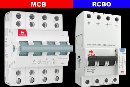
For example, just consider a circuit of the DOL (Direct on Line) starter, in the starter, the main components in Power Circuit are MCB, Contactor, and Overload relay. It shows the connection between the components through the block and the connection numbers in the components were connected with a straight horizontal line which is known as a conductor (wire).
This simply represents the wire connection between the components by intersecting the line in the connection number point. These are subassemblies made separately, i.e., Reassembled circuits or modules.
Wiring Schedule
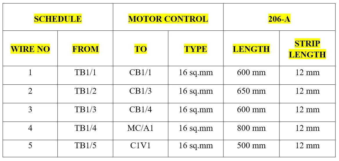
The wiring schedule defines the wire reference number, type, color, size, and the number of conductors, length, and amount of insulation stripping required will be mentioned in this schedule.
Actually, it is not a diagram it is a reference of the conductor which was used in a circuit for easy identification. In complex equipment, you may also find a table of interconnections which will give the starting and finishing reference points of each connection as well as other important information such as color, size, identify marking, and so on.
For example, below wiring schedule denotes the connection of Motor control applications which has the connection between two points (Where to where), Wire number, size, and type, strip length. With this, we can identify the wire connection in the circuit without deviating from any other connections in the circuit.
Block Diagram
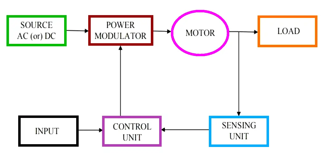
The block diagram is a functional drawing that is used to show and describes the main operating principles of the equipment and is usually drawn before the circuit diagram is drawn. It is considered as trial one where all the components are noted in the box-shaped block and they are interconnected. So this one shows the detail of the circuit function by this we can draw the actual circuit diagram later.
This block diagram will not give any detail of the exact wiring of the circuit, it will give only ideas for further development. Since a Block diagram is used for describes the function so it can be more useful for everyone to understand the operation than the circuit diagram.
Because if one wants to read the circuit diagram means one wants to know the symbols to understand the function and circuit. It is one of the easy ways to represent the function.
Parts List (Bill of Materials)
A Parts List or Bill of Materials is not a drawing but it must be a part of the drawing. This parts list gives the most important information in the circuit because it relates the components types to circuit drawing reference numbers and article code.
Parts List is also used to locate and cross-refer the actual component numbers to ensure you have the correct parts to commence a wiring job. It also shows the description of the component used in an electrical diagram which helps the reader to understand the details of the part.
Nowadays, in every electrical diagram, there is a standard for this parts list and every circuit diagram should have parts list in the drawing sheet.
Below is a simple example of a parts list in a simple DOL starter circuit.
| REFERENCE NO | BIN | DESCRIPTION | CODE |
| C01 | A3 | KW CIRCUIT BREAKER | PKZ2/24-40-8 |
| MC | A4 | KW CONTACTOR | DIL 2AW41550 |
| TOL | A4 | KW OVERLOAD RELAY | Z1-63 |
Single Line Diagram (SLD)
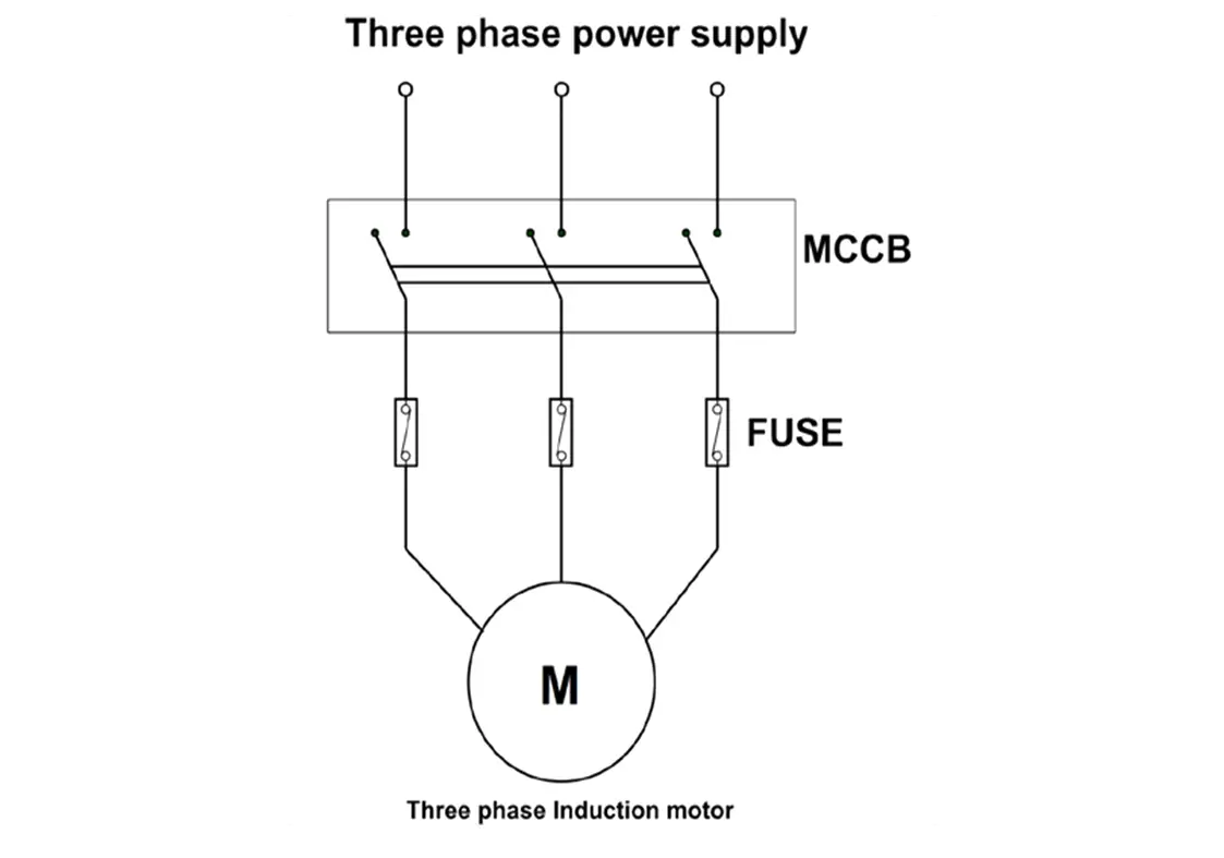
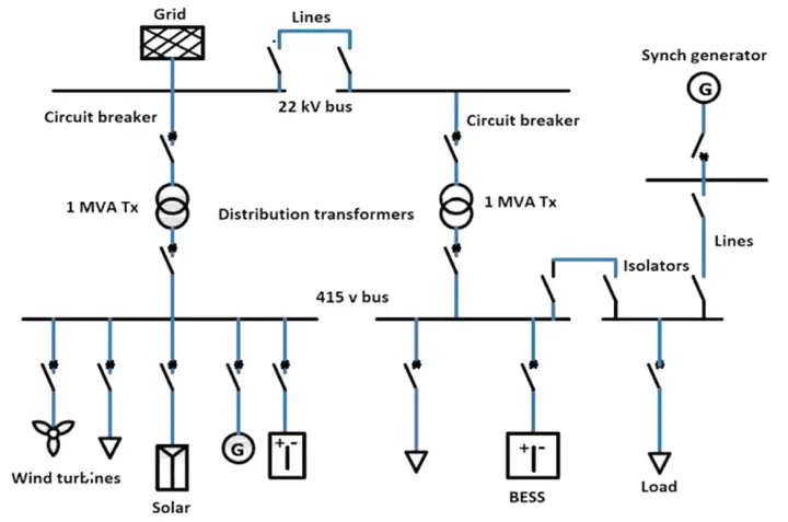
In Power engineering, a one-line diagram or single-line diagram is used for the representation of the three-phase systems. Single Line Diagram is used mainly in the application of power flow studies.
Electrical elements such as circuit breakers, transformers, contactors, bus bars, and conductor bars are shown by the standardized schematic symbols. Instead of representing three lines for three-phase systems only one line or conductor is used for describing the circuit breaker.
This single-line diagram indicates by means of single lines and standard symbols, the paths and interconnections, and components of an electrical circuit. It provides a basic understanding of how a portion of the electrical system functions in terms of the circuit’s physical components.
Single Line diagrams should be arranged so that the signal or transmission path from input to output proceeds in the flow from Left to right and Top to bottom.
The below diagram is an example of SLD where the power is transmitted through a transformer to the load where it is transmitted by a single line by connecting the main components and its flow is from Left to Right and Top to Bottom.
If you liked this article, then please subscribe to our YouTube Channel for Electrical, Electronics, Instrumentation, PLC, and SCADA video tutorials.
You can also follow us on Facebook and Twitter to receive daily updates.
Read Next:
- Why is IGBT used in VFD?
- Importance of Neutral Wire
- Induction Motor Problems
- Cables between VFD & Motor
- What is a Current Transformer?