Inst ToolsInst ToolsInst Tools
  • Courses
  • Automation
    • PLC
    • Control System
    • Safety System
    • Communication
    • Fire & Gas System
  • Instrumentation
    • Design
    • Pressure
    • Temperature
    • Flow
    • Level
    • Vibration
    • Analyzer
    • Control Valve
    • Switch
    • Calibration
    • Erection & Commissioning
  • Interview
    • Instrumentation
    • Electrical
    • Electronics
    • Practical
  • Q&A
    • Instrumentation
    • Control System
    • Electrical
    • Electronics
    • Analog Electronics
    • Digital Electronics
    • Power Electronics
    • Microprocessor
  • Request
Search
  • Books
  • Software
  • Projects
  • Process
  • Tools
  • Basics
  • Formula
  • Power Plant
  • Root Cause Analysis
  • Electrical Basics
  • Animation
  • Standards
  • 4-20 mA Course
  • Siemens PLC Course
Reading: Parking Lights PLC Program Explained with Video
Share
Font ResizerAa
Inst ToolsInst Tools
Font ResizerAa
  • Courses
  • Design
  • PLC
  • Interview
  • Control System
Search
  • Courses
  • Automation
    • PLC
    • Control System
    • Safety System
    • Communication
    • Fire & Gas System
  • Instrumentation
    • Design
    • Pressure
    • Temperature
    • Flow
    • Level
    • Vibration
    • Analyzer
    • Control Valve
    • Switch
    • Calibration
    • Erection & Commissioning
  • Interview
    • Instrumentation
    • Electrical
    • Electronics
    • Practical
  • Q&A
    • Instrumentation
    • Control System
    • Electrical
    • Electronics
    • Analog Electronics
    • Digital Electronics
    • Power Electronics
    • Microprocessor
  • Request
Follow US
All rights reserved. Reproduction in whole or in part without written permission is prohibited.
Inst Tools > Blog > PLC Tutorials > Parking Lights PLC Program Explained with Video

Parking Lights PLC Program Explained with Video

The parking lights PLC program designed for home automation to control the lights based on sensor input with video explanation.

Last updated: May 16, 2024 7:38 am
Editorial Staff
PLC Tutorials
No Comments
Share
5 Min Read
SHARE

The parking lights PLC program is designed for home automation to control the lights based on sensor input with video explanation.

Contents
Parking LightsPLC Program Explained with VideoInputs and OutputsLadder LogicProgram DescriptionSimulation Results

Note: This PLC logic is designed for learners to practice the ladder logics to improve their skills.

Parking Lights

Problem Statement:

Design a PLC ladder logic for the following application.

We are using one Button, one toggle Switch, and one sensor to control Lights, Exit Light, and Parking Light.

When the Lights are turned OFF in a building, an Exit Door Light remains ON for 15 seconds.

After that, the Parking Lot Lights get ON until the car gets out of the parking.

PLC Program Explained with Video

This PLC program video explains the parking lights logic with basics.

Inputs and Outputs

Digital Inputs:

Start Button: I0.0

Light OFF: I0.1

Sensor: I0.2

Digital Outputs:

Light 1: Q0.0

Light 2: Q0.1

Light 3: Q0.2

Light 4: Q0.3

Exit Light: Q0.4

Parking Light: Q0.5

Ladder Logic

Parking Lights PLC Program Explained with Video

Program Description

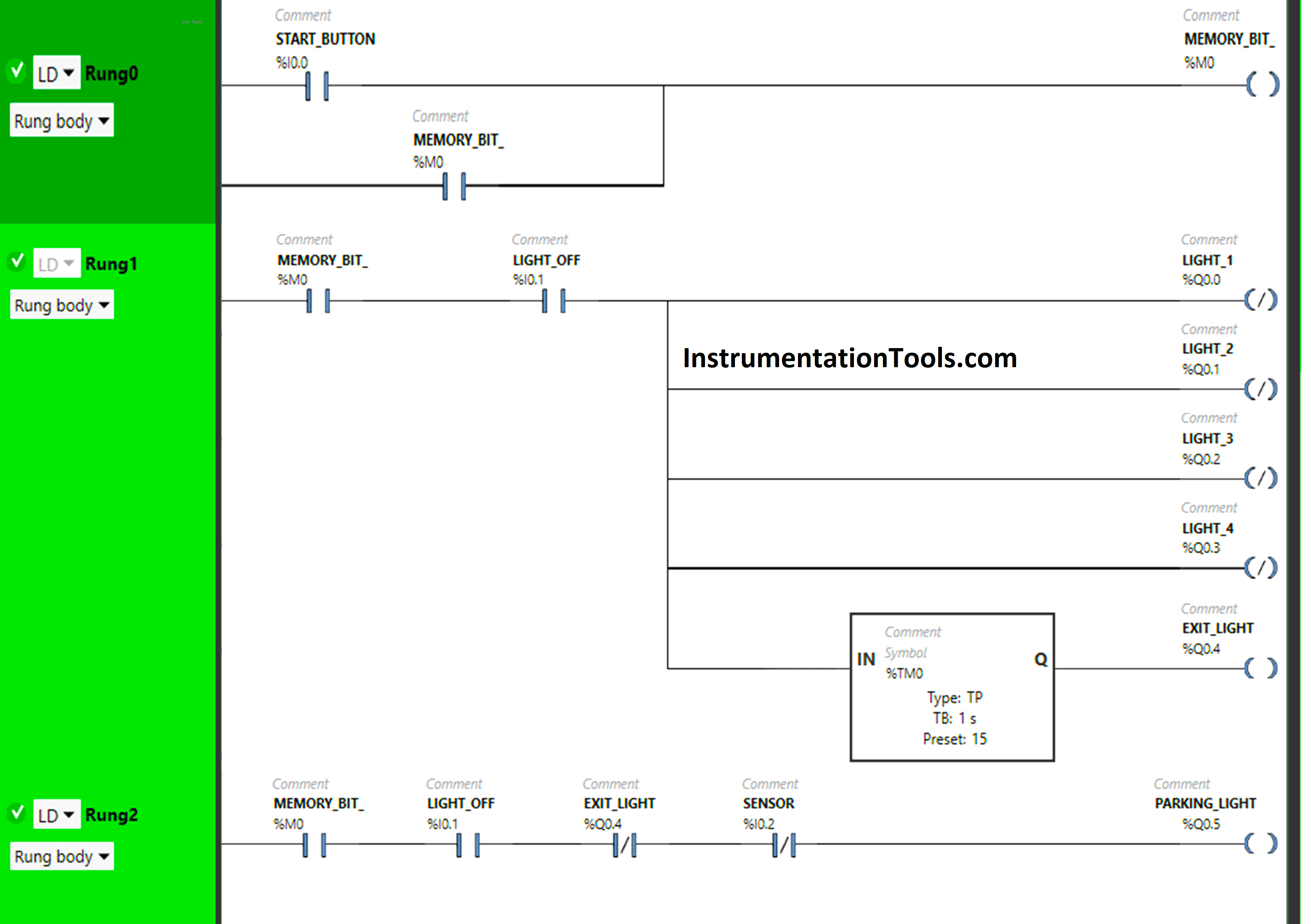
We have used Normally Open Contacts for the Start Button (I0.0, Lights OFF (I0.1), and Memory Bit (M0).

We have used Normally Closed Contacts for Exit Light (Q0.4) and Sensor (I0.2).

In Rung 0:

  1. Normally Open Contact is used for the Start Button (I0.0) to Turn ON Memory Bit (M0).
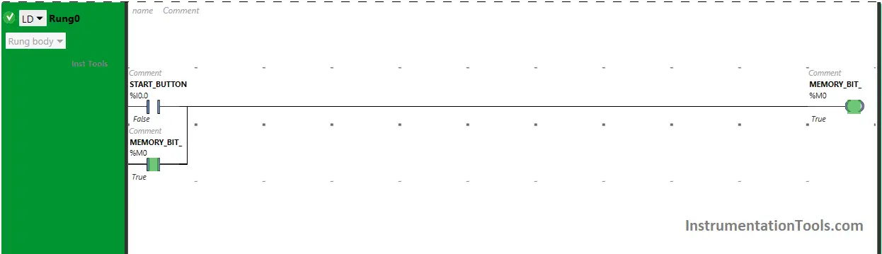
  2. Memory Bit (M0) is latched so that when the Start Button (I0.0) turns OFF, Memory Bit (M0) still remains ON.

In Rung 1:

  1. Normally Open Contacts are used for Memory Bit (M0) and Lights OFF (I0.1)  to Turn OFF the outputs Light 1 (Q0.0), Light 2 (Q0.1), Light 3 (Q0.2), Light 4 (Q0.3).
  2. Normally Open Contacts are used for Memory Bit (M0) and Lights OFF (I0.1)  to Turn ON the output Exit Light (Q0.4)
  3. Timer Function Block type TP is used to turn ON the output Exit Light (Q0.4) for a limited time.

In Rung 2:

  1. Normally Open Contacts are used for Memory Bit (M0) and Lights OFF (I0.1)  to Turn ON the output Parking Light (Q0.4).
  2. Normally Closed Contacts are used for the Exit Light (Q0.4) and Sensor (I0.2)  to Turn ON the output Parking Light (Q0.4)

Simulation Results

We simulate the PLC program and discuss the results. We may show the partial logic instead of the complete code.

Rung 0:

When the Start Button (I0.0) is pressed and released, Memory Bit (M0) turns ON and stores the data that the Start Button (I0.0) is pressed the first time as Memory bits store the data.

Program Parking Lot Control with PLC Simulator

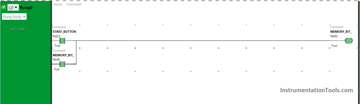
Memory Bit (M0) is latched so that when the Start Button (I0.0) is released, Memory Bit (M0) still remains ON.

Parking Lot Automation PLC Tutorial

Rung 1:

When Memory Bit  (M0) turns ON in Rung0, Normally Open Contact used for Memory Bit  (M0) in Rung1 will be in True State and will pass the signal through it.

A PLC program for parking lights

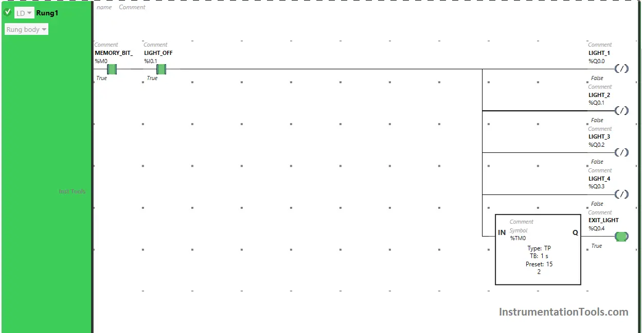
When Light OFF Switch (I0.1) is turned ON, the outputs Light 1 (Q0.0), Light 2 (Q0.1), Light 3  (Q0.2) and Light 4 (Q0.3) will turn OFF as Negated Coils are used for the outputs Light 1 (Q0.0), Light 2 (Q0.1), Light 3  (Q0.2) and Light 4 (Q0.3).

PLC Programming for Home Automation Parking Lights

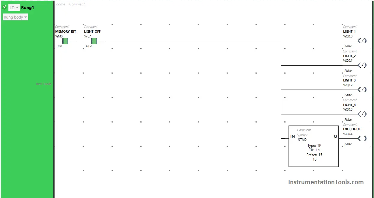
Also, when Memory Bit (M0) and Light OFF switch (I0.1) are turned ON, the output Exit Light (Q0.4) will turn ON ( immediately after Lights turn OFF in the building) but the output Exit Light (Q0.4) will turn OFF after some time as timer Function Block type TP is used to turn ON the output Exit Light (Q0.4) for a limited time.

The time is set to 15 seconds. After 15 seconds, the output Exit Light (Q0.4) will turn OFF (Exit Door Light turns OFF).

Rung 2:

home automation to control the lights based on sensor

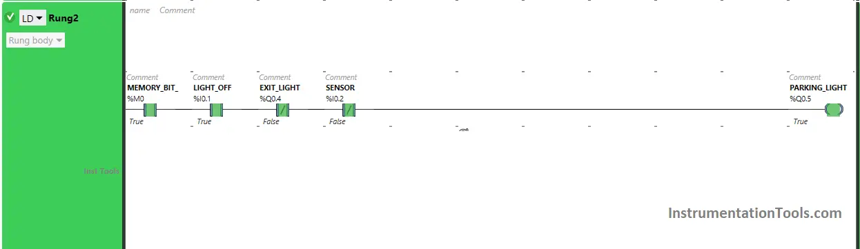
When Memory Bit (M0) turns ON, Light OFF switch (I0.1) is turned ON (Lights turns OFF in building), Exit Light (Q0.4) turns OFF (Exit door light turns OFF) and Sensor (I0.2) gets deactivated (Car gets out of parking), the output Parking Light (Q0.5) turns ON ( Parking lot lights gets ON).

If you liked this article, please subscribe to our YouTube Channel for PLC and SCADA video tutorials.

You can also follow us on Facebook and Twitter to receive daily updates.

Read Next:

  • Complex PLC Programming Examples
  • Traffic Lights PLC Program using Timers
  • PLC Programming for Trash Compactor
  • Playground Swing PLC Logic Programming
  • PLC Programming for the Pump to fill the tank
Don't Miss Our Updates
Be the first to get exclusive content straight to your email.
We promise not to spam you. You can unsubscribe at any time.
Invalid email address
You've successfully subscribed !

Continue Reading

All About Fieldbus Protocols
VFD Commissioning and Testing Procedure (Variable Frequency Drive)
Configuring and Usage of Cyclic Interrupts TIA Portal (OB 30+)
SCADA Interview Questions and Answers
PLC Programming to Control Lights in a Sequence
PLC Program for Alarm Indication in Process Control
Share This Article
Facebook Whatsapp Whatsapp LinkedIn Copy Link
Share
Leave a Comment

Leave a Reply Cancel reply

Your email address will not be published. Required fields are marked *

Stay Connected

128.3kFollowersLike
69.1kFollowersFollow
210kSubscribersSubscribe
38kFollowersFollow

Categories

Explore More

OB1 – Main Cyclic Organization Block in TIA Portal
What are Faceplates? How to Create a Faceplate? HMI Visualization
PUT Command in Siemens PLC – TIA Portal Basics
How to Wire a Field instrument to Control Room with Example
Types of Limit Switches – Principle, Advantages, Disadvantages
PLC Programming Examples on Industrial Automation
How to Retrieve PLC Project From Memory Card?
Vijeo Designer software – Import and Export

Keep Learning

Causes of PLC Stop Mode

Various Causes for PLC Going in Stop Mode

What is PLC

What is a PLC? – Programmable Logic Controller

Free Siemens PLC Training Course

Free Siemens PLC Training Course

memory types in siemens plc

#13 PLC Best Practices – Disable Unused Communication Ports

Boolean Logic to PLC Programming

Boolean Logic to PLC Programming

PLC Commissioning and Testing

PLC Commissioning and Testing Procedure (Programmable Logic Controller)

PLC Best Practices

#1 PLC Best Practices – Split PLC Code into Modules

Best 100 PLC Projects for Final Year Engineering Students

Best 100 PLC Projects for Final Year Engineering Students

Learn More

Digital input signals in safety circuits

1oo2 Evaluation Safety Instruction in Safety PLC

3 Wire RTD Connections

RTD Sensor Connections

Digital Electronics Multiple Choice Questions

Counters Objective Questions

Top 100 Electrical Machines Projects for Electrical Engineers

Top 100 Electrical Machines Projects for Electrical Engineers

Power Electronics Objective Questions

Thyristor Family Objective Questions and Answers

Heat Detector Testing Procedure

Heat Detector Testing Procedure

RTD lead resistances Wiring

Resistance Temperature Detectors Working Principle

Mechanical Temperature Indicators (MTI) Problem

Mechanical Temperature Indicators (MTI) Problem

Menu

  • About
  • Privacy Policy
  • Copyright

Quick Links

  • Learn PLC
  • Helping Hand
  • Part Time Job

YouTube Subscribe

Follow US
All rights reserved. Reproduction in whole or in part without written permission is prohibited.
Welcome Back!

Sign in to your account

Username or Email Address
Password

Lost your password?