Automatic bending machine
This is PLC Program for automatic bending machine for exhaust pipe.
Problem Description
The bending of exhaust pipes is to be controlled using PLC. The bending procedure must not start unless both the pipe and connector fitting are present. If a part is defective or not present this is indicated by an indicator light.
Write PLC program for this application using ladder diagram language.
Problem Diagram
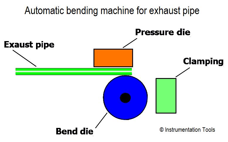
Solution
- A proximity switch is used to detect weather a pipe is present or not. Then pipe will be clamped in position via the solenoid valve.
- And if the connector fitting is also present, bending process will be ON after 2 second.
- If pipe is not detected for 5 second, error lamp will glow and it can be acknowledged by pressing acknowledge button.
List of Inputs/Outputs
List of Inputs
- I0.0 :- Start PB
- I0.1 :- Stop PB
- I0.2 :- Pipe detected
- I0.3 :- Connector detected
List of Outputs
- Q0.0 :- Cycle ON
- Q0.1 :- Clamping ON
- Q0.2 :- Error lamp
Ladder diagram for Automatic Bending Machine

Program Description
In this program we have used Siemens S7-300 PLC and TIA Portal Software for programming.
Network 1 :-
Main cycle can be started by pressing start PB (I0.0).And can be stop by pressing stop PB (I0.1).
Network 2 :-
When exhaust pipe and connector are detected, after 2sec clamping process (Q0.1) will be ON.
Network 3 :-
If cycle is not ON or pipe is not detected, clamping Q0.1) will be OFF.
Network 4 :-
If pipe is not detected for 5 sec, error lamp (Q0.2) will be ON.
Network 5 :-
Error lamp (Q0.2) can be acknowledged by pressing acknowledges PB (I0.3).
Note :- Above application may be different from actual application. We can also make this application by using other PLC also. This example is only for explanation purpose. This is the bending machine for exhaust pipes in industries; we can use this concept in other examples also.
All parameters and graphical representations considered in this example are for explanation purpose only, parameters or representation may be different in actual applications. Also all interlocks are not considered in the application.
Author : Bhavesh
If you liked this article, then please subscribe to our YouTube Channel for PLC and SCADA video tutorials.
You can also follow us on Facebook and Twitter to receive daily updates.
Read Next:
PLC Selective Execution of Application
Tank Heating Control using Heater
PLC Separate Different Size Objects