Fluid power diagrams and schematics require an independent review because they use a unique set of symbols and conventions.
Fluid power diagrams and schematics require an independent review because they use a unique set of symbols and conventions.
Fluid Power Diagrams and Schematics
Different symbology is used when dealing with systems that operate with fluid power. Fluid power includes either gas (such as air) or hydraulic (such as water or oil) motive media. Some of the symbols used in fluid power systems are the same or similar to those already discussed, but many are entirely different.
Fluid power systems are divided into five basic parts:
- Pumps,
- Reservoirs,
- Actuators,
- Valves, and
- Lines.
Pumps
In the broad area of fluid power, two categories of pump symbols are used, depending on the motive media being used (i.e., hydraulic or pneumatic). The basic symbol for the pump is a circle containing one or more arrow heads indicating the direction(s) of flow with the points of the arrows in contact with the circle.
Hydraulic pumps are shown by solid arrow heads. Pneumatic compressors are represented by hollow arrow heads. Figure 19 provides common symbols used for pumps (hydraulic) and compressors (pneumatic) in fluid power diagrams.
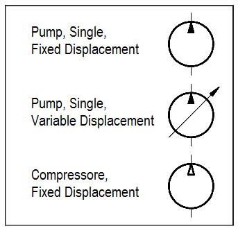
Figure 19 Fluid Power Pump and Compressor Symbols
Reservoirs
Reservoirs provide a location for storage of the motive media (hydraulic fluid or compressed gas). Although the symbols used to represent reservoirs vary widely, certain conventions are used to indicate how a reservoir handles the fluid.
Pneumatic reservoirs are usually simple tanks and their symbology is usually some variation of the cylinder shown in Figure 20.
Hydraulic reservoirs can be much more complex in terms of how the fluid is admitted to and removed from the tank. To convey this information, symbology conventions have been developed. These symbols are in Figure 20.
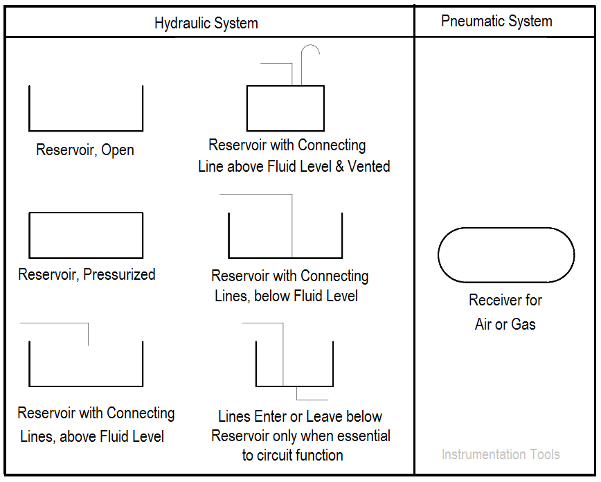
Figure 20 Fluid Power Reservoir Symbols
Actuator
An actuator in a fluid power system is any device that converts the hydraulic or pneumatic pressure into mechanical work. Actuators are classified as linear actuators and rotary actuators.
Linear actuators have some form of piston device. Figure 21 illustrates several types of linear actuators and their drawing symbols.
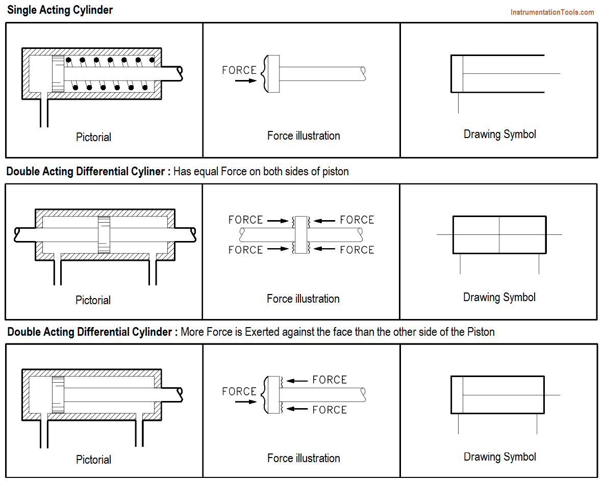
Figure 21 Symbols for Linear Actuators
Rotary actuators are generally called motors and may be fixed or variable. Several of the more common rotary symbols are shown in Figure 22. Note the similarity between rotary motor symbols in Figure 22 and the pump symbols shown in Figure 19.
The difference between them is that the point of the arrow touches the circle in a pump and the tail of the arrow touches the circle in a motor.
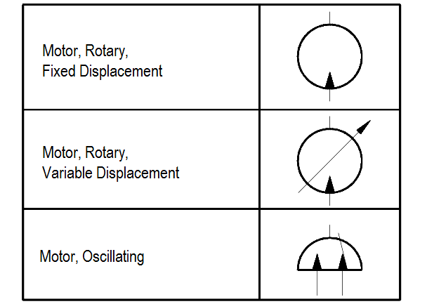
Figure 22 Symbols for Rotary Actuators
Piping
The sole purpose of piping in a fluid power system is to transport the working media, at pressure, from one point to another. The symbols for the various lines and termination points are shown in Figure 23.
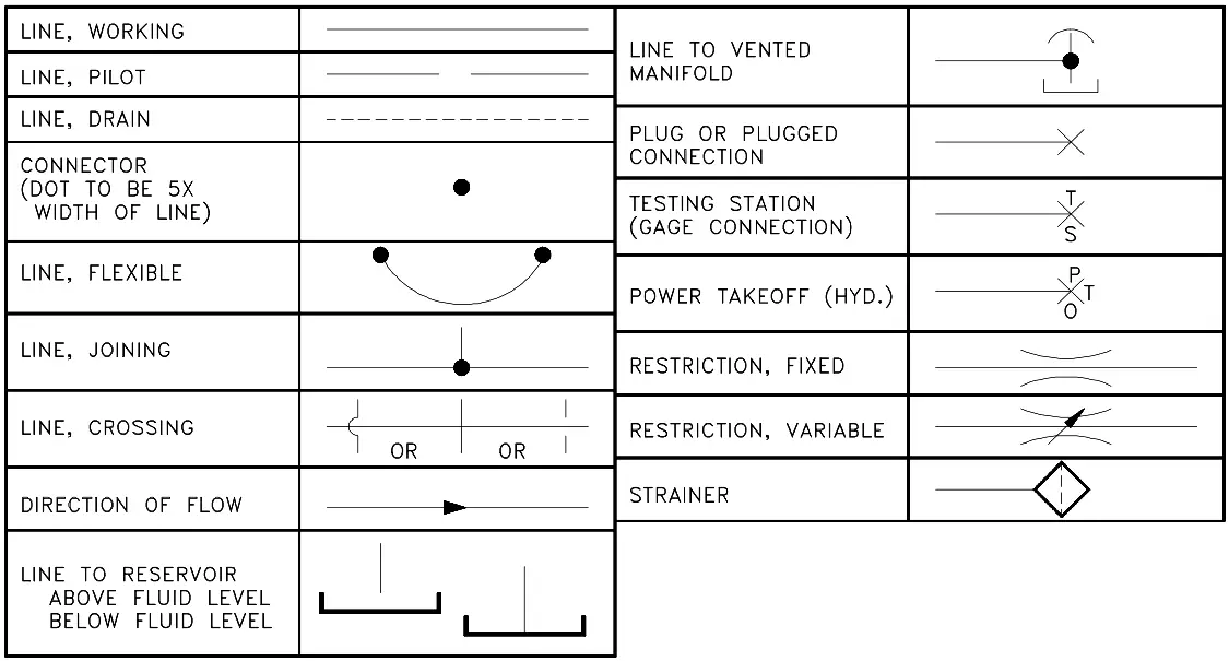
Figure 23 Fluid Power Line Symbols
Valves
Valves are the most complicated symbols in fluid power systems. Valves provide the control that is required to ensure that the motive media is routed to the correct point when needed. Fluid power system diagrams require much more complex valve symbology than standard P&IDs due to the complicated valving used in fluid power systems.
In a typical P&ID, a valve opens, closes, or throttles the process fluid, but is rarely required to route the process fluid in any complex manner (three- and four-way valves being the common exceptions). In fluid power systems it is common for a valve to have three to eight pipes attached to the valve body, with the valve being capable of routing the fluid, or several separate fluids, in any number of combinations of input and output flowpaths.
The symbols used to represent fluid power valves must contain much more information than the standard P&ID valve symbology. To meet this need, the valve symbology shown in the following figures was developed for fluid power P&IDs.
Figure 24, a cutaway view, provides an example of the internal complexity of a simple fluid power type valve. Figure 24 illustrates a four-way/three-position valve and how it operates to vary the flow of the fluid. Note that in Figure 24 the operator of the valve is not identified, but like a standard process fluid valve the valve could be operated by a diaphragm, motor, hydraulic, solenoid, or manual operator.
Fluid power valves, when electrically operated by a solenoid, are drawn in the de-energized position. Energizing the solenoid will cause the valve to shift to the other port. If the valve is operated by other than a solenoid or is a multiport valve, the information necessary to determine how the valve operates will be provided on each drawing or on its accompanying legend print.
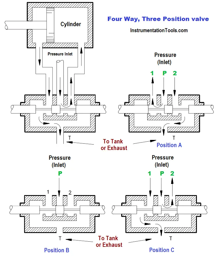
Figure 24 Valve Operation
Refer to Figure 25 to see how the valve in Figure 24 is transformed into a usable symbol.
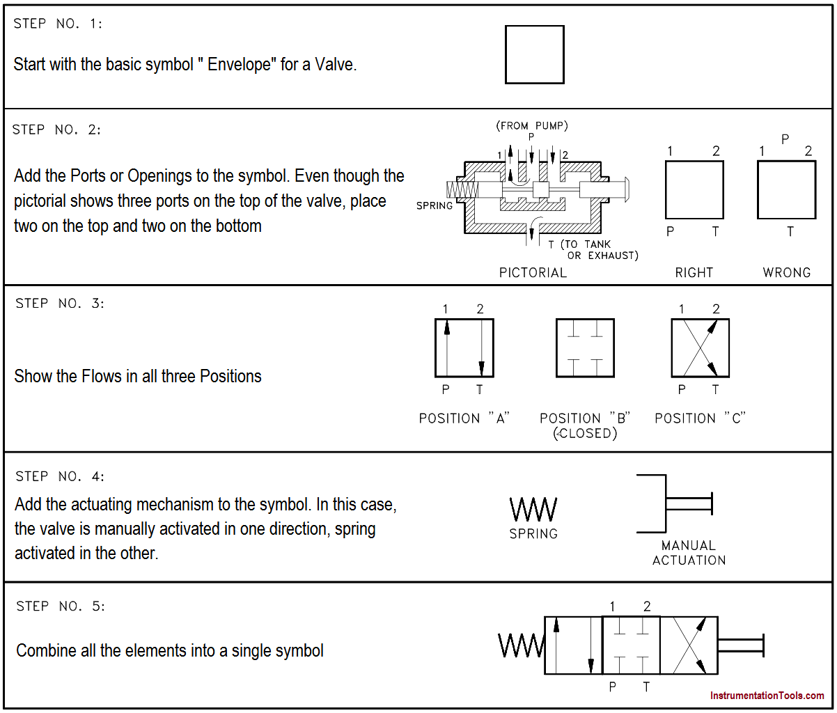
Figure 25 Valve Symbol Development
Figure 26 shows symbols for the various valve types used in fluid power systems.

Figure 26 Fluid Power Valve Symbols
Reading Fluid Power Diagrams
Using the symbology previously discussed, a fluid power diagram can now be read. But before reading some complex examples, let’s look at a simple hydraulic system and convert it into a fluid power diagram.
Using the drawing in Figure 27, the left portion of Figure 28 lists each part and its fluid power symbol. The right side of Figure 28 shows the fluid power diagram that represents the drawing in Figure 27.

Figure 27 Simple Hydraulic Power System

Figure 28 Line Diagram of Simple Hydraulic Power System
With an understanding of the principles involved in reading fluid power diagram, any diagram can be interpreted. Figure 29 shows the kind of diagram that is likely to be encountered in the engineering field.
To read this diagram, a step-by-step interpretation of what is happening in the system will be presented.

Figure 29 Typical Fluid Power Diagram
The first step is to get an overall view of what is happening. The arrows between A and B in the lower right-hand corner of the figure indicate that the system is designed to press or clamp some type of part between two sections of the machine. Hydraulic systems are often used in press work or other applications where the work piece must be held in place.
With the basic function understood, a detailed study of the diagram can be accomplished using a step-by-step analysis of each numbered local area in the diagram.
LOCAL AREA NUMBER 1
Symbol for an open reservoir with a strainer. The strainer is used to clean the oil before it enters the system.
LOCAL AREA NUMBER 2
Fixed displacement pump, electrically operated. This pump provides hydraulic pressure to the system.
LOCAL AREA NUMBER 3
Symbol for a relief valve with separate pressure gage. The relief valve is spring operated and protects the system from over pressurization. It also acts as an unloader valve to relieve pressure when the cylinder is not in operation. When system pressure exceeds its setpoint, the valve opens and returns the hydraulic fluid back to the reservoir. The gage provides a reading of how much pressure is in the system.
LOCAL AREA NUMBER 4
Composite symbol for a 4-way, 2-position valve. Pushbutton PB-1 is used to activate the valve by energizing the S-1 solenoid (note the valve is shown in the de-energized position). As shown, the high pressure hydraulic fluid is being routed from Port 1 to Port 3 and then to the bottom chamber of the piston. This drives and holds the piston in local area #5 in the retracted position. When the piston is fully retracted and hydraulic pressure builds, the unloader (relief) valve will lift and maintain the system’s pressure at setpoint.
When PB-1 is pushed and S-1 energized, the 1-2 ports are aligned and 3-4 ports are aligned. This allows hydraulic fluid to enter the top chamber of the piston and drive it down. The fluid in the bottom chamber drains though the 3-4 ports back into the reservoir. The piston will continue to travel down until either PB-1 is released or full travel is reached, at which point the unloader (relief) valve will lift.
LOCAL AREA NUMBER 5
Actuating cylinder and piston. The cylinder is designed to receive fluid in either the upper or lower chambers. The system is designed so that when pressure is applied to the top chamber, the bottom chamber is aligned to drain back to the reservoir. When pressure is applied to the bottom chamber, the top chamber is aligned so that it drains back to the reservoir.
Types of Fluid Power Diagrams
Several kinds of diagrams can be used to show how systems work. With an understanding of how to interpret Figure 29, a reader will be able to interpret all of the diagrams that follow.
A pictorial diagram shows the physical arrangement of the elements in a system. The components are outline drawings that show the external shape of each item. Pictorial drawings do not show the internal function of the elements and are not especially valuable for maintenance or troubleshooting. Figure 30 shows a pictorial diagram of a system.

Figure 30 Pictorial Fluid Power Diagram
A cutaway diagram shows both the physical arrangement and the operation of the different components. It is generally used for instructional purposes because it explains the functions while showing how the system is arranged. Because these diagrams require so much space, they are not usually used for complicated systems.
Figure 31 shows the system represented in Figure 30 in cutaway diagram format and illustrates the similarities and differences between the two types of diagrams.

Figure 31 Cutaway Fluid Power Diagram
A schematic diagram uses symbols to show the elements in a system. Schematics are designed to supply the functional information of the system. They do not accurately represent the relative location of the components. Schematics are useful in maintenance work, and understanding them is an important part of troubleshooting.
Figure 32 is a schematic diagram of the system illustrated in Figure 30 and Figure 31.

Figure 32 Schematic Fluid Power Diagram


thanks
Hello, I have some questions about a really “old” hydraulic system I have purchased. I intend to use it with another machine. However, I cannot figure out what some of the items are and hesitate to turn it on. Would you know of someone who could help me identify the setup?
Thank you.
thank you. for detail practical overview.
Thanks for useful information.
nicely explained, thank you very much.
Very usefull
Thank you
Useful information to understanding the working principles.
Thank you for sharing
thanks