The fundamental principle invoked in shielding signal conductor(s) from external electric fields is that no substantial electric field can exist within a solid conductor.
Electric fields exist due to imbalances of electric charge. If such an imbalance of charge ever were to exist within a conductor, charge carriers (typically electrons) in that conductor would quickly move to equalize the imbalance, thus eliminating the electric field.
Capacitive Coupling Effects
Another way of saying this is to state that electric fields only exist between points of different potential, and therefore cannot exist between equi-potential points. Thus, electric flux lines may be found only in the dielectric (insulating media) between conductors, not within a solid conductor:

This also means electric flux lines cannot span the diameter of a hollow conductor:

The electrical conductivity of the hollow sphere’s wall ensures that all points on the circumference of the sphere are equi-potential to each other.
This in turn prohibits the formation of any electric flux lines within the interior air space of the hollow sphere. Thus, all points within the hollow sphere are shielded from any electric fields originating outside of the sphere.
The only way to allow an external electric field to penetrate a hollow conductor from the outside is if that conductive shell is left “floating” with respect to another conductor placed within the shell.
In this case the lines of electric flux do not exist between different points on the conductive sphere, but rather between the shell of the sphere and the conductor at the center of the sphere because those are the points between which a potential difference (voltage) exists.
To illustrate:

However, if we make the hollow shell electrically common to the negative side of the high-voltage source, the flux lines inside the sphere vanish, since there is no potential difference between the internal conductor and the conductive shell:

If the conductor within the hollow sphere is elevated to a potential different from that of the high-voltage source’s negative terminal, electric flux lines will once again exist inside the sphere, but they will reflect this second potential and not the potential of the original high-voltage source.
In other words, an electric field will exist inside the hollow sphere, but it will be completely isolated from the electric field outside the sphere.
Once again, the conductor inside is shielded from external electrostatic interference:

If conductors located inside the hollow shell are thus shielded from external electric fields, it means there cannot exist any capacitance between external conductors and internal (shielded) conductors.
If there is no capacitance between conductors, there will never be capacitive coupling of signals between those conductors, which is what we want for industrial signal cables to protect those signals from external interference.
All this discussion of hollow metal spheres is just an introduction to a discussion of shielded cable, where electrical cables are constructed with a conductive metal foil wrapping or conductive metal braid surrounding the interior conductors.
Thus, the foil or braid creates a conductive tube which may be connected to ground potential (the “common” point between external and internal voltage sources) to prevent capacitive coupling between any external voltage sources and the conductors within the cable:

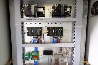
The following photograph shows a set of signal cables with braided shield conductors all connected to a common copper “ground bus.”
This particular application happens to be in the control panel of a 500 kV circuit breaker, located at a large electrical power substation where strong electric fields abound:

This next photograph shows a four-conductor USB cable stripped at one end, revealing a metalfoil shield as well as silver-colored wire strands in direct contact with the foil, all wrapped around the four colored power and signal conductors:

At the terminating end we typically twist the loose shield conductor strands together to form a wire which is then attached to a ground point to fix the cable’s shield at Earth potential.
It is very important to ground only one end of a cable’s shield, or else you will create the possibility for a ground loop: a path for current to flow through the cable’s shield resulting from differences in Earth potential at the cable ends. Not only can ground loops induce noise in a cable’s conductor(s), but in severe cases it can even overheat the cable and thus present a fire hazard:

An important characteristic of capacitively-coupled noise voltage is that it is common-mode in nature: the noise appears equally on every conductor within a cable because those conductors lie so close to each other (i.e. because the amount of capacitance existing between each conductor and the noise source is the same).
One way we may exploit this characteristic in order to help escape the unwanted effects of capacitive coupling is to use differential signaling. Instead of referencing our signal voltage to ground, we let the signal voltage “float.”
The following schematic diagram illustrates how this works:

The lack of a ground connection in the DC signal circuit prevents capacitive coupling with the AC voltage from corrupting the measurement signal “seen” by the instrument. Noise voltage will still appear between either signal wire and ground as a common-mode voltage, but noise voltage will not appear between the two signal wires where our signal of interest exists.
In other words, we side-step the problem of common-mode noise voltage by making common-mode voltage irrelevant to the sensor and to the signal receiver. Some industrial data communications standards such as EIA/TIA-485 (RS-485) use this technique to minimize the corrupting effects of electrical noise.