Range Setting (Re-range)
Range setting (re-ranging) refers to setting the scale for the 4 mA and 20 mA points. This scale is usually referred to as “calibrated range” or “calibration range”. That is, at what input shall the transmitter analog output be 4 mA; Lower Range Value (LRV) often referred to as “zero” meaning 0%, and at what input shall it be 20 mA; Upper Range Value (URV), sometimes called “full scale” meaning 100%.
Note that the term “span” is not the same as URV. Span is the magnitude of difference between URV and LRV. For instance, if LRV is 20 and URV is 100, the span is 80. Since Fieldbus, PROFIBUS, and WirelessHART do not use 4-20 mA, range setting is not required for such devices in most applications.
Note that calculating what the output current value should be is done in firmware in the transmitter microprocessor. It is a mathematical function.
Internally the 4-20 mA/HART transmitter computes:
Percentage = (PRIMARY_VARIABLE – LRV) / (URV – LRV) * 100 …..in [%]
Analog Current = (PRIMARY_VARIABLE – LRV) / (URV – LRV) * 16 + 4 ….in [mA]
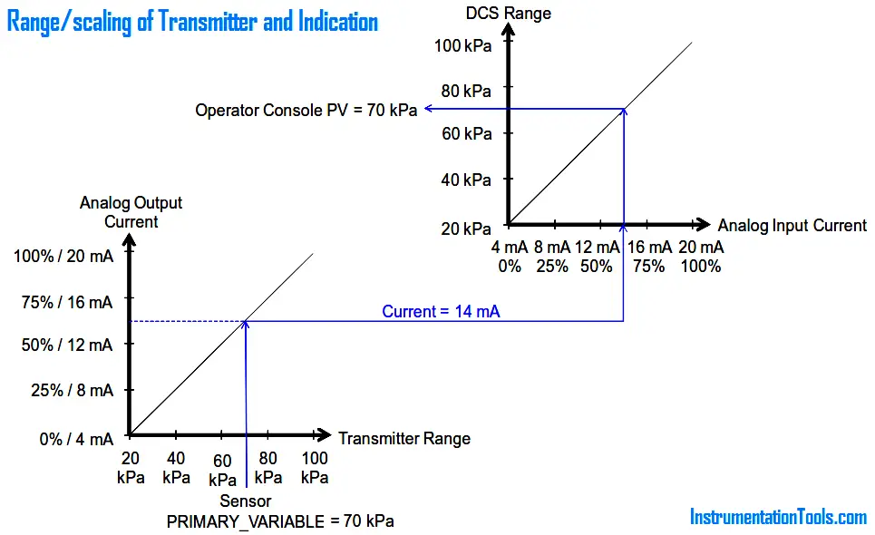
Internally the 4-20 mA control system, recorder, or indicator computes:
Percentage = (Current – 4) / 16 * 100 in [%]
PV = (Current – 4) / 16 * (URV – LRV) + LRV in [E.U.]
The analog 4-20 mA output of a transmitter is limited to the LRV to URV range. Thus the analog output does not benefit from the full LSL to USL capability of the sensor.
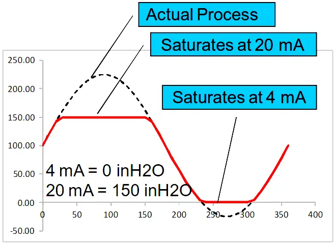
Fig : In an analog signal system the measurement is confined within range values
However, FOUNDATION fieldbus, PROFIBUS, and WirelessHART transmitters as well as the digital output of 4-20 mA/HART transmitters are not limited to the LRV to URV range, but can benefit from full LSL to USL capability of the sensor.
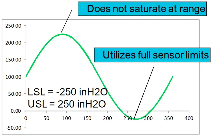
Fig : In a digital bus signal system the measurement enjoys the full sensor limits
Transmitter range setting is done without applying input, and therefore can be done remotely from a central location. For instance, set range of pressure transmitter to get 4 mA when input is 0 bar and 20 mA when pressure is 40 bar.
Range must be set within the Lower Sensor Limit (LSL) and Upper Sensor Limit (USL). Transmitters usually also have a minimum span to be observed.
The difference between URV and LRV must exceed the minimum span, or else the analog output resolution and percentage accuracy is too poor since with a small span the quantization error from the sensor A/D converter gets amplified too much. The transmitter will reject range setting and sensor trim attempts not observing the LSL, USL, and minimum span limits.
The sensor limits depend mostly on physical restrictions of the sensor. The sensor limits cannot be changed, therefore they are always read-only. Different sensors have different sensor limits.
For example, various RTDs and thermocouples have different sensor limits. In temperature applications, a sensor type with sufficient sensor limits has to be selected to accommodate the range of the application.
Since the range limits are physical and cannot be changed, to get wider sensor limits accommodate a wider range, it is necessary to purchase a new sensor.
Similarly, pressure transmitters have a selection of sensor modules with different range limits from the lowest “draft” up to very high pressures. To get wider sensor limits to accommodate a wider range, it is necessary to purchase a new sensor.
ANSI/ISA–51.1 Definition of Terms
zero elevation:
For an elevated-zero range, the amount the measured variable zero is above the lower range-value.
zero suppression:
For a suppressed-zero range, the amount the measured variable zero is below the lower range-value.
Range setting is only applicable to transmitter with 4-20 mA analog output. That is, for 4-20 mA/HART transmitters, not for pure digital solutions like FOUNDATION fieldbus (FF) or WirelessHART transmitters.
The reason being that FF and WirelessHART transmitters has no 4-20 mA analog output, therefore there is no need to set 4 mA and 20 mA range points. For 4-20 mA systems the range is set in both the transmitter and controller.
For FF and PROFIBUS the range is set in the controller, and need not be set in the transmitter which can lead to some confusion for beginners. The only exception for FF, WirelessHART, and PROFIBUS transmitters may be for differential pressure (DP) flow and level measurement where the end-points of the DP scale (e.g. 0250 inH2O in XD_SCALE) and corresponding flow or level scale (e.g. 0-400 bbl/day in OUT_SCALE).
This also enables DP transmitters to locally indicate in flow or level units. FF and PROFIBUS devices have provision for setting a range in the transmitter even though it may not be used for the application.
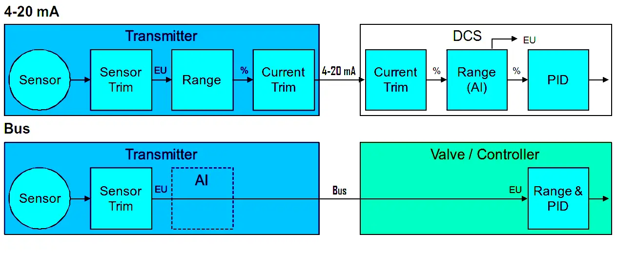
Fig : An analog signal system requires range, current trims, and scaling. A digital bus system does not.
However, the nominal operating range has to be specified also for FOUNDATION fieldbus and WirelessHART transmitters for sizing purposes when purchasing, such that the device supplier can pick the appropriate sensor model. There is also a need to select the desired engineering unit in the device.
The DCS may need a range set in database as scaling end-points for bar graphs and trend and will also need a range for PID control even though there is no range in the FOUNDATION fieldbus or WirelessHART device. In control applications, level is usually expressed in percentage of full tank.
The output of both the FF transducer block and the AI function block is engineering unit. For most applications there is no need to set range in either block in order to get the PV. However, many systems use the range in the FF transmitter AI block to scale the faceplates bargraphs.
A narrower range may optionally be set to increase the resolution of the faceplate bargraph. If a range is set in the AI block, the percentage of range can be seen from the FIELD_VAL parameter.
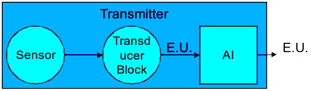
Fig : Digital transmitters internally operate in engineering units
There are typically two ways to set the range of the transmitter:
- Direct numeric value entry
- To applied input
Direct numeric value entry
Direct numeric value entry means the desired lower and upper range values are simply entered in from device software or handheld field communicator, and sent to the transmitter, for instance, entering the 20 to 100 kPa.
To applied input
Range setting to applied input requires a physical input corresponding to the desired range value to be applied to the transmitter. This is sometimes used in level measurement applications.
Because the mounting (datum) of the level transmitter plays a part in the range, the range shall be adjusted at site, it cannot be done in a lab. Basically it is a zero cancelation such as DP wet leg.
For instance, first the tank is emptied to its lower level and then the “set PV LRV command” is sent to the transmitter to set the lower range value to whatever the input happens to be.
For instance for a DP level transmitter, if the pressure is 20 kPa when the tank is empty (the pressure tap is slightly below the datum), this becomes the new lower range value, thus ensuring the reading is 0% and analog output current is 4 mA whenever the tank is empty.
Conversely, next the tank is filled to its upper level and then the “set PV URV” command is sent to the transmitter to set the upper range value to whatever the input happens to be.
For instance, if the pressure is 100 kPa when the tank is full, this becomes the new upper range value, thus ensuring the reading is 100% and analog output current is 20 mA whenever the tank is full. In between the reading is linear.
Note that the technician need not know what the physical input is, just that the tanks is full and empty respectively.
The set PV LRV command is also common to cancel wet-leg for DP transmitters in all kinds of application including flow. The set PV LRV and set PV URV commands are equivalent to pushing the ‘zero’ and ‘span’ buttons respectively found on some transmitters.
ANSI/ISA–51.1 Definition of Terms
range: The region between the limits within which a quantity is measured, received, or transmitted, expressed by stating the lower and upper range-values.
For example: a) 0 to 150°F b) –20 to +200°F c) 20 to 150°C
range-value, lower (LRV) : The lowest value of the measured variable that a device is adjusted to measure.
range-value, upper (URV) : The highest value of the measured variable that a device is adjusted to measure.
range-limit, lower (LSL) : The lowest value of the measured variable that a device can be adjusted to measure.
range-limit, upper (USL) : The highest value of the measured variable that a device can be adjusted to measure.
span: The algebraic difference between the upper and lower range-values. For example: Range 0 to 150°F, Span 150°F Range –20 to 200°F, Span 220°F Range 20 to 150°C, Span 130°C
Note : FOUNDATION fieldbus uses the term “scale” for “range”
Article Source : Eddl
Read Next:
Smart Transmitter Tutorial Part 1
Smart Transmitter Tutorial Part 2
Smart Transmitter Tutorial Part 3
PLS SIR, I WANT TO KNOW HOW TO ZERO CHECK A LOCAL LEVEL TRANSMITTER{ ANALOGUE LEVEL TRANSMITTER}