Calibration can be carried out using a handheld communicator in the field, a laptop on the bench in the workshop, or from intelligent device management (IDM) software as part of an asset management system.
Electronic Device Description Language (EDDL) is the technology used by device manufacturers to define how the system shall display the device information and functions to the technician. EDDL makes the calibration of smart transmitters and other intelligent devices easier.

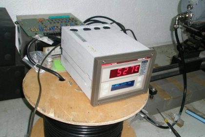
Figure: Smart Transmitter
This tutorial explains the common principles of calibration, re-ranging, and trim as they apply to various kinds of transmitters.
The detail procedure varies slightly depending on the measurement done, sensing principle, and each manufacturer.
Calibration
By definition, the term “calibrate” means several different things:
- Set the range (scale)
- Trim (correct) the sensor (transducer) reading or current output against a standard
- Simply compare the sensor (transducer) reading or current output against a standard to see how large the error is without correcting (trim) it.
This is often done in five points, increasing and decreasing. If the error is too large, the transmitter may be trimmed or replaced.
ANSI/ISA–51.1 Definition of Terms
Calibrate: To ascertain outputs of a device corresponding to a series of values of the quantity which the device is to measure, receive, or transmit. Data so obtained are used to:
- Determine the locations at which scale graduations are to be placed;
- Adjust the output, to bring it to the desired value, within a specified tolerance;
- Ascertain the error by comparing the device output reading against a standard.
Calibrating Smart Transmitters
The term “calibration” in the context of smart/intelligent transmitters is often misunderstood.
In the days of analog transmitters calibration meant applying a physical input and turning the trim potentiometers to adjust the transmitter so that the analog output current becomes correct according to the desired measurement range.
Once smart transmitters appeared, this “calibration” process was divided into three parts:
- Sensor trim
- Range setting (re-ranging)
- Current trim
The reason for separating these functions is that the range can be changed without applying a physical input.
This was a huge time and cost saver and one of the major reasons for the rapid adoption of smart transmitters.
However, do not confuse “sensor trim” with “range setting”. Both are part of calibration, but two very different things.
In the view of many, range setting is more like configuration than calibration.
Sensor Trim (Digital Trim)
Over time all sensors drift. Depending on the type of sensor it may be due to extreme pressure or temperature, vibration, material fatigue, contamination, or other factors. Sensor reading may also be offset due to mounting position.
Sensor trim is used to correct the digital reading as seen in the device local indicator LCD and received over the digital communication.
For instance, if pressure is 0 bar but transmitter reading shows 0.03 bar, then sensor trim is used to adjust it back to 0 bar.
Sensor trim can also be used to optimize performance over a smaller range than was originally trimmed in the factory.
The basic principle for calibration (sensor trim) of all transmitters is the same:
- Apply a known input
- Tell the transmitter what it is
- The transmitter calculates internal correction factors
- The transmitter uses the new correction factors to compute a new correct measurement reading
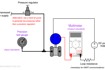
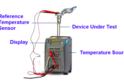
Sensor trim requires the technician to apply a physical input to the transmitter. Therefore the technician must either do sensor trim in the field at the process location, or the transmitter has to be brought back into the workshop to perform sensor trim.
This applies to 4-20 mA/HART, WirelessHART, FOUNDATION fieldbus, as well as PROFIBUS transmitters.
Sensor trim in the field is easiest done using a handheld communicator connected to the running bus which is supported by 4-20 mA/HART, WirelessHART, and FOUNDATION fieldbus.
For PROFIBUS-PA the trim command can either be sent from the control system, or the transmitter can temporarily be disconnected from the running bus to perform the sensor trim.
Typically there are three forms of sensor trim:
- Zero sensor trim
- Lower sensor trim
- Upper sensor trim
Zero trim requires the physical input applied to be zero, this is often used with pressure transmitters For best accuracy perform sensor trim in two points, close to lower range value and upper range value. This is where lower and upper sensor trim is used.
A known physical input is applied to the transmitter to perform the sensor trim, the technician enters the applied value (on a computer or handheld communicator) communicated to the transmitter, allowing the transmitter to correct itself.
The physical input values applied for lower and upper sensor trim respectively are stored in the transmitter memory and are referred to as Lower Sensor Trim Point and Upper Sensor Trim Point respectively.
Sensor trim requires a very accurate input to be applied. The factory calibration equipment is usually more accurate than the portable calibrators at site.
Moreover, transmitters these days are typically very stable. Therefore, sensor trim of brand new transmitters is rarely done at commissioning.
Note that sensor trim is done in firmware in the transmitter microprocessor; it is not done in the sensor itself.
The trim is really a mathematical function, adjusting numerical bias and gain factors.
That is, it is the sensor reading after the A/D conversion which is trimmed, not the sensor hardware
Sensor trim is the aspect of calibration which this article focuses on. That is:
- Pressure calibration
- Flow calibration
- Temperature calibration
- Level calibration
- Etc.
Sensor Trim Points
The purpose of the (CAL_POINT) parameters is to tell at which points sensor trim was last done, and to perform sensor trim points sensor trim if needed.
If the sensor trim points parameters are 0 and 360 mbar this means these are the points at which it was calibrated (sensor trim).
The transmitter may still be able to measure -600 to +600, but remember the transmitter is now extrapolating so it may not be full accuracy, but it may be OK anyway.
This is not uncommon. If sensor trim is performed at -600 and +600 greater accuracy may be achieved.
Note that the sensor trim points are not just “set”; they are NOT range configuration parameters. These two parameters are written when sensor trim is performed.
The transmitter then remembers these points were the trim was made. Typically there is a sensor trim wizard (“method”) that takes the technician step by step through the calibration process and it is this sensor trim wizard that writes the sensor trim point parameters.
Article Source: Eddl
Read Next:
Smart Transmitter Tutorial Part 1
Smart Transmitter Tutorial Part 2
Smart Transmitter Tutorial Part 3


hello sir gud mng what is proffibus cable and proffibus pa proffibus dp like available pls explain
Hello,
Please, I want to know if a level transmitter is calibrated in the range of 12 to 22 inches of water and a level indicating controller has also been calibrated in the range of 10 to 20 inches of water. If the level transmitter is reading 17 inches of the actual level of the liquid, what will the controller indicate?
can anyone help me about yta 320 yokogawa temperature transmitter field bus
how i verify it ?