This article covers the calibration of all type Pressure indicating devices like pressure gauge, compound gauge, and vacuum gauge according to the standard DKD-R-6-1.
The DKD R-6-1 guideline is created by the Technical Committee ‘Pressure and Vacuum’, in cooperation with the PTB and the accredited calibration laboratories.
The guideline has been approved by the Board of the DKD.
Full form of acronym ‘DKD’ is Deutscher Kalibrierdienst.
English translation: German Calibration Service.
Full form of acronym ‘PTB’ is Physikalisch-Technische Bundesanstalt.
English translation: Physics Technical Federal Agency
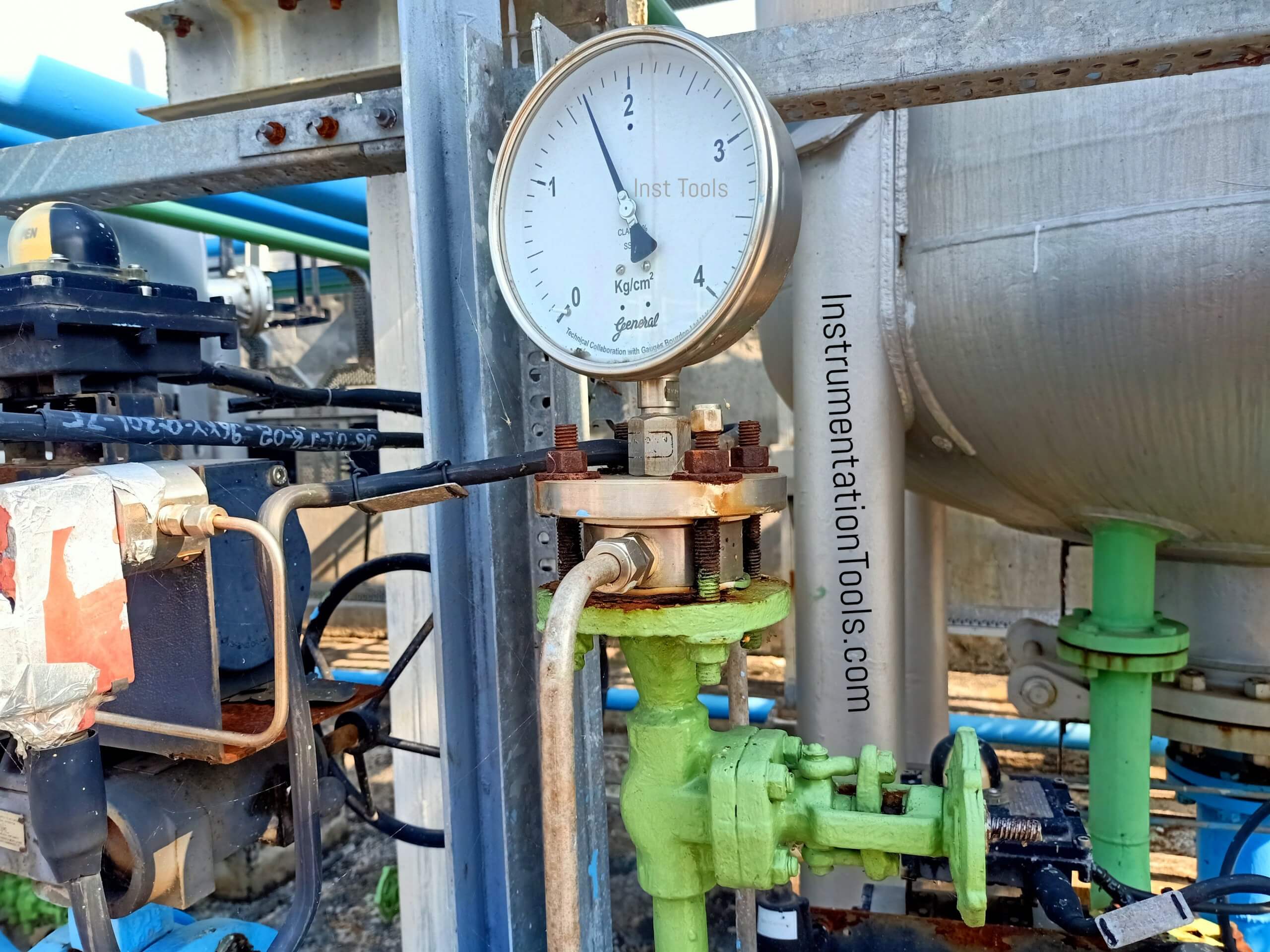
Pressure Gauge
A pressure gauge is used to measure and indicate pressure greater than ambient using ambient pressure as the reference point.
Vacuum Gauge
A vacuum gauge is used to measure and indicate pressure less than ambient using ambient pressure as the reference point.
Compound Gauge
A compound gauge is used to measure and indicate pressure both greater than and less than ambient using ambient pressure as the reference point.
Calibration according to Standard DKD-R-6-1
One of the ways of Calibration of Pressure Gauge is by comparison method.
The comparison of the measured value between calibration item and standard can be done in two ways:
First Method
Adjustment of the Pressure according to the indication of the Calibration Item
I.e. required Set Point is attained on Calibration Item and corresponding reading is measure on Standard Pressure Gauge
Second Method
Adjustment of the Pressure according to the indication of the Standard
I.e. required Set Point is attained on Standard Pressure Gauge and corresponding reading is measure on Calibration Item.
Calibration Procedure
Before Calibration of Pressure Gauge put the Teflon Tape on the thread area of the gauge properly. Make sure that the tape is not in the air path, otherwise, it will resist the pressure supply.
Select proper Standard Pressure Gauge (The standard shall have accuracy 1/3rd or better than UUC). More details provided in article Selection of Master Instruments.
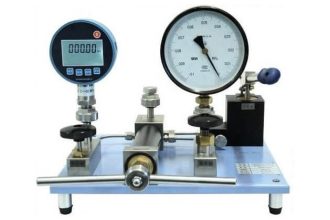
Mount Standard Pressure Gauge and UUC (Unit under Calibration) on Pressure calibrator (Hand Pump or Hydraulic Pump) using proper connector.
Both UUC and Standard should be in same Units such as bar, kg/cm2 etc. If not, unit conversion should be followed properly.
Initially adjust both UUC and standard to zero reading.
Equally distribute calibration points into 5 points (0%, 25%, 50 %, 75% and 100%) for the gauges accuracy of greater than 0.6%F.S and 9 points (0%, 10%, 30%, 40%, 50%, 60% , 70%,90%, 100% )for the gauges accuracy of less than 0.6% F.S .However additional points can be taken as per the customer request.
Calibration items that are calibrated with positive and negative gauge pressure should at least be calibrated at two points in the negative range (e.g. at -1 bar and -0.5 bar); the remaining measurement points should be calibrated in the positive range.
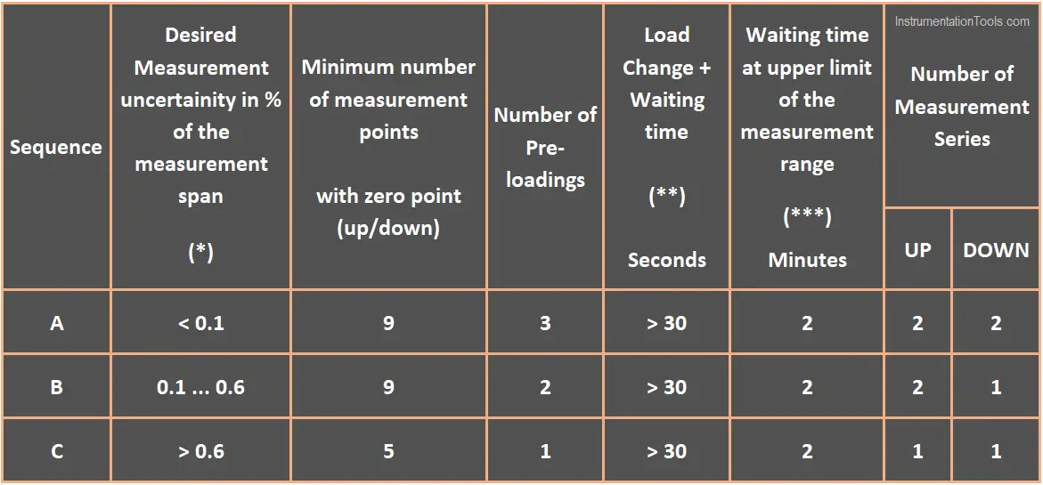
(*) The reference to the measurement span was chosen in order to allow the selection of the sequence (necessary calibration effort) from the table since the accuracy specifications provided by the manufacturers are usually related to the measurement span. In the case of measuring devices for which specifications of the measurement value or assembled specifications are stated, Table 1 is to be applied, using the specification limit (e.g. of the measurement span).
(**) In any case, one has to wait until steady state conditions (sufficiently stable indication of the standard and the calibration item) are reached.
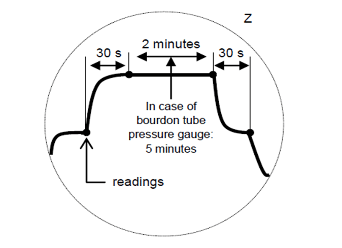
(***) For Bourdon tube pressure gauges, a waiting time of 5 minutes is to be observed. The waiting times can be reduced for quasi-static calibrations (piezoelectric sensor principle).
Selection of Sequence A, B, C depends on accuracy of UUC.
As most of the time Pressure Gauge is used in a Specific range in Industry. So we need to do Preloading to free the Pointer of the Pressure gauge
Pre Loading – Increase Pressure up to full scale & decrease it to zero of UUC. Repeat this 1, 2 or 3 times (according to accuracy of UUC) to make pointer movement free.
We should wait at least for 30 seconds to note readings of the Pressure Gauge. As Pressure is generated by forcing air or liquid, it needs some time to become stable and attained steady-state condition. The waiting time for the upper limit of the measuring range is 2 minutes.
Measurement cycles of Gauge accuracy less than 0.1 % –> 2 UP cycles and 2 DOWN cycles
Measurement cycles of Gauge accuracy 0.1 % to 0.6% –> 2 UP cycles and 1 DOWN cycles
Measurement cycles of Gauge accuracy more than 0.6% –> 1 UP cycles and 1 DOWN cycles
Up Cycle is measured from Minimum pressure range to Maximum Pressure Range
Down Cycle is measured from Maximum pressure range to Minimum Pressure Range
CALIBRATION – UP CYCLE
- Increase Pressure/Vacuum by operating pump to set the calibration point on UUC gauge.
- When pointer of UUC Gauge reach first calibration point note down both UUC & standard reading. Wait for 30 seconds to note down reading. Wait for 2 Minutes for upper limit of measuring range.
- Slowly increase the pressure/vacuum to set next set point .Write down reading Standard reading & UUC reading.
- Repeat this procedure for remaining calibration points.
- This completes Up cycle of calibration of Pressure/vacuum Gauge
CALIBRATION – DOWN CYCLE
- For Down Cycle, Last calibration point of Up Cycle is first point of Down Cycle.
- Slowly decrease the pressure/vacuum to set next set point. Write down reading Standard reading & UUC reading. Wait for 30 seconds to note down reading. Wait for 2 Minutes for upper limit of measuring range.
- Repeat this procedure for the remaining calibration points.
- This completes Down Cycle of calibration of Pressure/vacuum Gauge
Repeat Up and Down cycle according to accuracy of Pressure Gauge as mention above.
Visual Representation of Cycles
Sequence A is for Pressure Gauge accuracy less than 0.1 %. Pre-Loading should be done 3 times (Pre-Loading is defined above).
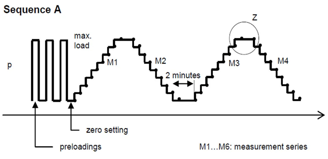
UUC and Master are set to Zero. M1 is first UP cycle with 9 measurement points. Dot in above diagram represent Measurement Point.
30 seconds waiting time in between them. 2 minutes waiting time as Maximum range I.e. 2 minutes waiting time between Calibration Up-cycle and Down-Cycle.
M2 is first Down cycle with 9 measurement points. Again 2 minutes waiting time.
M3 is Second Up Cycle and M4 is Second Down Cycle.
Sequence B is for Pressure Gauge accuracy from 0.1 % to 0.6 %.
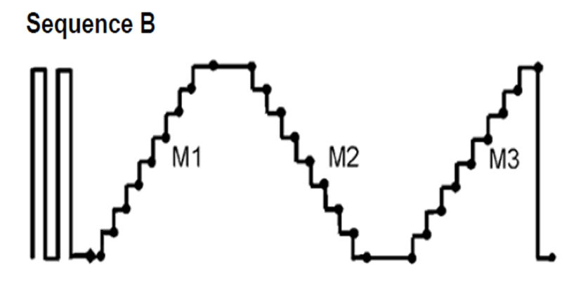
Explanation is similar to Sequence A. 2 Up cycles and 1 down cycle.
Sequence C is for Pressure Gauge accuracy above 0.6 %.
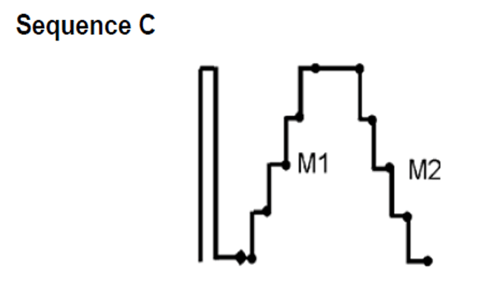
Explanation is similar to Sequence A. 1 Up cycle and 1 down cycle.
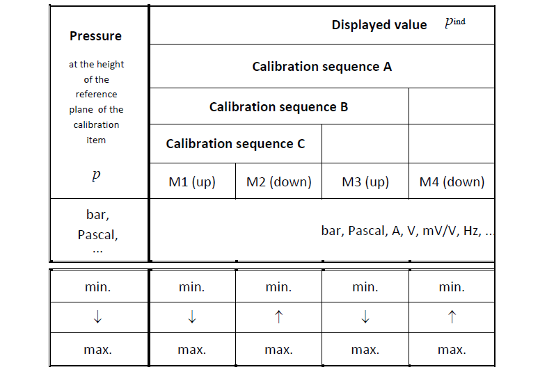
Summary of Calibration Cycles
Reference for all Images: Standard DKD R-6-1
If you liked this article, then please subscribe to our YouTube Channel for Instrumentation, Electrical, PLC, and SCADA video tutorials.
You can also follow us on Facebook and Twitter to receive daily updates.
Read Next:


Why DKD is the standard accteptance? and How many calibration standard about pressure gauge?