Inst ToolsInst ToolsInst Tools
  • Courses
  • Automation
    • PLC
    • Control System
    • Safety System
    • Communication
    • Fire & Gas System
  • Instrumentation
    • Design
    • Pressure
    • Temperature
    • Flow
    • Level
    • Vibration
    • Analyzer
    • Control Valve
    • Switch
    • Calibration
    • Erection & Commissioning
  • Interview
    • Instrumentation
    • Electrical
    • Electronics
    • Practical
  • Q&A
    • Instrumentation
    • Control System
    • Electrical
    • Electronics
    • Analog Electronics
    • Digital Electronics
    • Power Electronics
    • Microprocessor
  • Request
Search
  • Books
  • Software
  • Projects
  • Process
  • Tools
  • Basics
  • Formula
  • Power Plant
  • Root Cause Analysis
  • Electrical Basics
  • Animation
  • Standards
  • 4-20 mA Course
  • Siemens PLC Course
Reading: Multimeter – What Do Digits and Counts Mean?
Share
Notification Show More
Font ResizerAa
Inst ToolsInst Tools
Font ResizerAa
  • Courses
  • Design
  • PLC
  • Interview
  • Control System
Search
  • Courses
  • Automation
    • PLC
    • Control System
    • Safety System
    • Communication
    • Fire & Gas System
  • Instrumentation
    • Design
    • Pressure
    • Temperature
    • Flow
    • Level
    • Vibration
    • Analyzer
    • Control Valve
    • Switch
    • Calibration
    • Erection & Commissioning
  • Interview
    • Instrumentation
    • Electrical
    • Electronics
    • Practical
  • Q&A
    • Instrumentation
    • Control System
    • Electrical
    • Electronics
    • Analog Electronics
    • Digital Electronics
    • Power Electronics
    • Microprocessor
  • Request
Follow US
All rights reserved. Reproduction in whole or in part without written permission is prohibited.
Inst Tools > Blog > Calibration > Multimeter – What Do Digits and Counts Mean?

Multimeter – What Do Digits and Counts Mean?

While buying Multimeter Digits and Counts is an important factor. These are two different ways to express the same thing.

Last updated: September 28, 2022 3:24 pm
Saurabh Vaidya
Calibration
4 Comments
Share
6 Min Read
SHARE

Many times we come across terms, ‘abc’ Multimeter is 3 ½, 4 ½, 6 ½, 7 ½ digits or 2000, 4000, 6000 counts. (‘abc’ means the manufacturer of multimeter)

Contents
Multimeter DigitsMultimeter CountsAccuracy

We also come across the accuracy of ‘abc’ Multimeter is ‘0.15% + 2 digit’.

While buying Multimeter Digits and Counts is an important factor

What do these counts and digits mean?

Digits and counts are two different ways to express the same thing.

Multimeter Digits

Take an e.g. of 3 ½ digit Multimeter.

The format is given as a whole number followed by a fraction, usually a 1/2 or a 3/4.   

The whole number represents how many digits displayed from 0 to 9.

The fraction is ½ or a ¾.

Fraction ½ means the most significant digit for each range can be 0 or 1.

A ¾ means the most significant digit for each range is greater than 1.

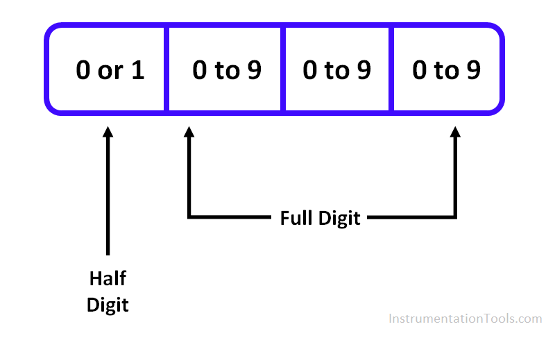
3 ½ digit Multimeter can display three complete digits and one ½ digit. Three complete digits can have any numbers from 0 to 9 and one ½ digit can have only 0 or 1.

Three Positions of digits can display 0 to 9 numbers and leftmost position can only display 0 or 1 number in 3 ½ digit Multimeter.

Similarly for 4 ½,6 ½, 7 ½ digit Multimeter displays complete 0 to 9 numbers on  four, six ,seven positions respectively and leftmost position displays only 0 or 1 number.

An illustration for 3 ½ Digit Multimeter Display (shown below)

3 ½ Digit Multimeter Display

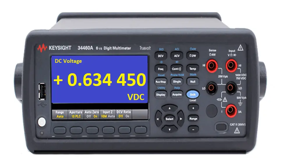
A 6 ½ Digit Multimeter Display (as shown below)

6 ½ Digit Multimeter Display

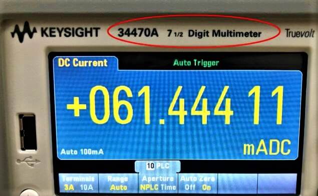
A 7 ½ Digit Multimeter Display (as shown below)

7 ½ Digit Multimeter Reading

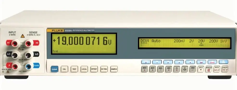
An 8 ½ Digit Multimeter Display (as shown below)

8 ½ Digit Multimeter

Multimeter Counts

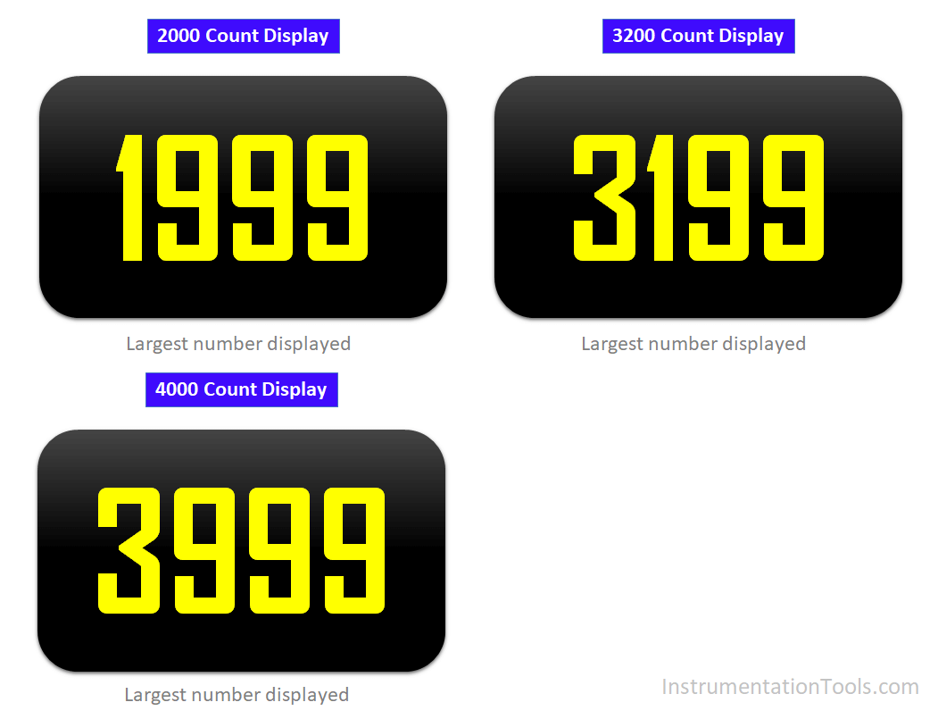
If the display of Multimeter is 2000 counts. It can display digits from 0000 to 1999 counts. i.e. 3 ½ digit Multimeter.

If the display of Multimeter is 20000 counts. It can display digits from 00000 to 19999 counts. i.e. 4 ½ digit Multimeter.

Therefore, Digits and counts are two different ways to express same thing.

Counts are ignoring any decimal points and polarity signs.

Many newer Multimeters don’t have a restriction of 0 or 1 at leftmost digits.

Example

Display of Multimeter is 4000 counts. It can display digits from 0000 to 3999 counts. I.e. leftmost digit can have 0,1,2,3 digits.

So, it is more practical to describe a Multimeter by its counts rather than digits.

Counts tell you what the instrument can display before it changes to the next range.

For example, suppose a Multimeter is of 20000 counts (4 ½ digit Multimeter). This means the range changes when it hits 20000 on display.

A 20000 count meter can read 19.999 V on the display, but when it tries to display 20 V, it will read 020.00 V instead or simply 20.00 V.

The Multimeter moves to the next range mean one digit of resolution is lost.

Generally 2000 Count Multimeter (3 ½ digit Multimeter) have range 200.0 mV, 2.000 V, 20.00 V, 200.0 V.

Generally 6000 Count Multimeter have range 600.0 mV, 6.000 V, 60.00 V, 600.0 V

The count refers to the limit of the highest value the Multimeter will display for each range.

As soon as a measured value reaches this limit, the range will move up and the resolution will be downgraded by a factor of 10, that is, the decimal place will be moved to the right one spot.

Multimeter Counts

If we had a Multimeter that was designed to measure up to 1000V with a 40000 count, then, the ranges and resolution can be as follows:

0.0000 to 3.9999 with a resolution of 0.0001

4.000 to 39.999 with a resolution of 0.001

40.00 to 399.99 with a resolution of 0.01

400.0 to 1000.0 with a resolution of 0.1

Accuracy

The accuracy of Multimeter is written as “0.15% + 2 digits”

Means 0.15 % of indicated value + 2 × Resolution

Example

Reading of Multimeter at 1 volt is 1.005 V

Resolution is 0.001 V

Accuracy = (0.15% × 1.005) + (2× 0.001)

Accuracy = 0.0035 V

If you liked this article, then please subscribe to our YouTube Channel for Instrumentation, Electrical, PLC, and SCADA video tutorials.

You can also follow us on Facebook and Twitter to receive daily updates.

Read Next:

  • Calibration Organizations
  • Calibration Master Instruments
  • Stroke Checking Procedure
  • Smart Transmitter Sensor Trim
  • As-Left As-Found Calibration
Don't Miss Our Updates
Be the first to get exclusive content straight to your email.
We promise not to spam you. You can unsubscribe at any time.
Invalid email address
You've successfully subscribed !

Continue Reading

How to Calibrate Load Cells in Weighing Applications?
Oxidation-Reduction Potential (ORP) Sensor Calibration Procedure
What is Bump Testing ?
Hybrid Level Measurement Principle, Selection, Installation, Limitations and Calibration
Stability and Uniformity of Temperature Bath
Bently Nevada Vibration Probes Functional Testing
Share This Article
Facebook Whatsapp Whatsapp LinkedIn Copy Link
Share
4 Comments
  • John says:
    January 10, 2022 at 4:19 pm

    Accuracy = (0.15% × 1.005) + (2× 0.001)
    Accuracy = 0.0035 V

    Shouldn’t that be 0.0034V?

    Reply
  • Sophia says:
    November 1, 2022 at 7:03 am

    Well explained with the help of examples.

    Reply
  • Olivia says:
    November 1, 2022 at 7:05 am

    Good explanation. Helpful in clearing the basics.

    Reply
  • Chuck says:
    May 24, 2023 at 5:06 am

    Thank You..

    Reply

Leave a Reply Cancel reply

Your email address will not be published. Required fields are marked *

Stay Connected

128.3kFollowersLike
69.1kFollowersFollow
210kSubscribersSubscribe
38kFollowersFollow

Categories

Explore More

Pressure Transmitter Calibration Procedure
NIST Traceability
Foundation Fieldbus Transmitter Calibration
Displacer (buoyancy) Level Transmitter Principle, Limitations, Design, Installation & Calibration
Instruments Calibration Procedures
Current to Pressure (I/P) Converter Calibration Procedure
Calibration MCQ – Terminology and Glossary Questions
Difference between Calibration and Ranging

Keep Learning

RTD Testing Methods

RTD Testing Methods in Calibration Laboratory

Specific-Conductance-Calibration-Procedure

Specific Conductance Calibration Procedure

Selection of Industrial Temperature Calibrator

Selection of Industrial Temperature Calibrator

pressure-switch-calibration-procedure

Pressure Switch Calibration Procedure

Pressure Gauge Calibration according to Standard DKD-R-6-1

Pressure Gauge Calibration according to Standard DKD-R-6-1

level-transmitter-calibration-procedure

Level Transmitter Calibration Procedure

Installation and Calibration of Pressure Transmitter

Installation and Calibration of Pressure Transmitter

Closed-tank-DP-Level-Transmitter-with-wet-leg-elevation-zero-direct-mount-Calibration

Closed tank DP Level Transmitter with wet leg elevation zero direct mount Calibration

Learn More

cut-away control valve

How Globe Valves Work ?

Coil Type Timers in Siemens PLC Programming

Coil Type Timers in Siemens PLC Programming

Instrumentation and Control Course

Free Instrumentation Course for Trainee Engineers

Calculate-current-4-20ma-from-process-varibale-pv

Calculate Current (4-20ma) from Process variable PV

Inductor Principle

Inductance and Inductive Reactance

Fieldbus Segment

Basics of Foundation Fieldbus

Electrical Machines Questions and Answers

Rotating Machines Electrical Quiz

Door Locking System - PLC Applications Examples

Door Locking System – PLC Applications Examples

Menu

  • About
  • Privacy Policy
  • Copyright

Quick Links

  • Learn PLC
  • Helping Hand
  • Part Time Job

YouTube Subscribe

Follow US
All rights reserved. Reproduction in whole or in part without written permission is prohibited.
Welcome Back!

Sign in to your account

Username or Email Address
Password

Lost your password?