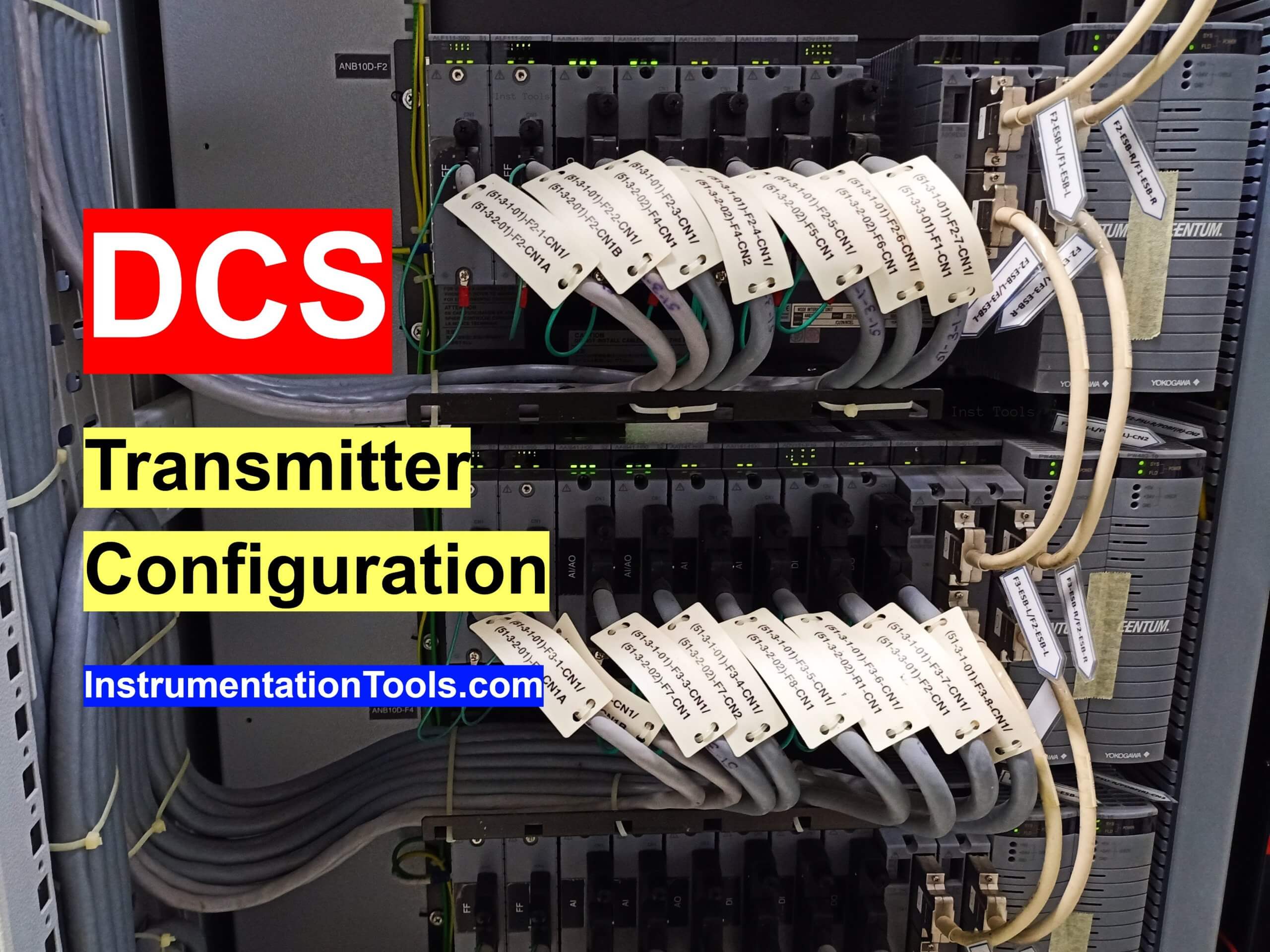
In this article, we will learn how to do the configuration of analog input (transmitter) in the Yokogawa Centum VP DCS system. The DCS abbreviation is Distributed Control System.
Here we will configure a new transmitter in the Centum VP software.
Yokogawa DCS Tutorials
You need to have some details before configuring a new transmitter in the DCS system.
First, you need the details of the Analog Input Card where you are going to connect the new transmitter.
Also, you need the location details of this analog input card in the system cabinet like FCS number, IOM details, Node number, and then AI card slot number.
You can get the details from the Nest Loading list.
Also Read: What is Nest Loading List?
DCS Configuration of Analog Input (Transmitter)
The below animation will help you to understand the configuration procedure of a new flow transmitter in the Yokogawa DCS.
Follow the below steps to configure a new transmitter in DCS.
Step 1: Open Field Control Station
Open the System View software.
You may have one or more number of FCS (Field Control Station) in your plant.
Go to the required FCS where you want to add a new transmitter. The FCS selection depends on your plant area and the location of the new transmitter. Check your plant control system documents for more details.

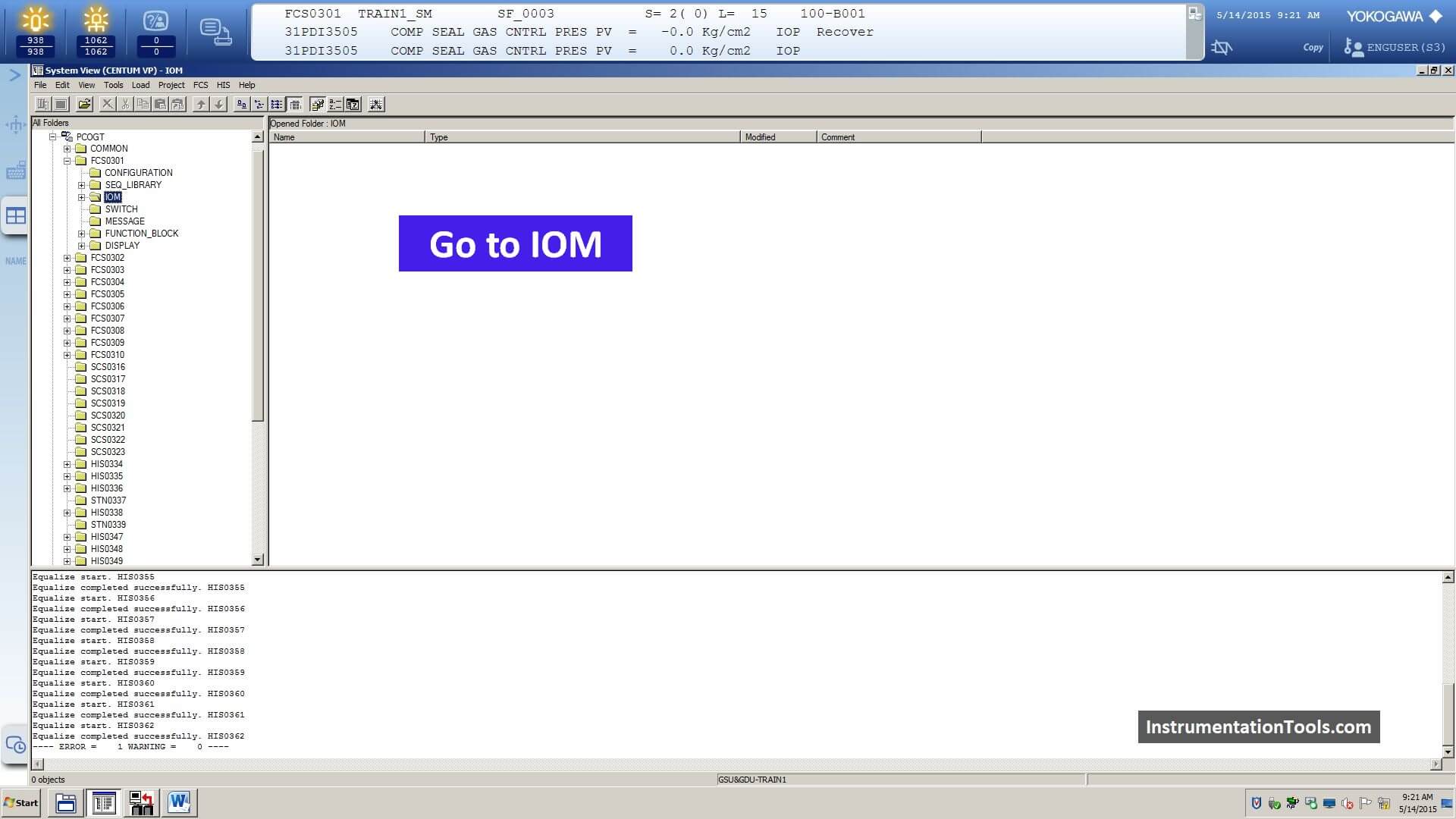
Step 2: Go to IOM
Next, go to the IO module page in the selected FCS.
You have to expand the FCS folder and again expand the IOM folder.
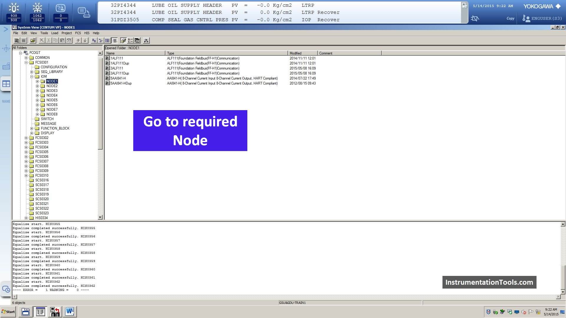
Step 3: Go to Node
Next, You have to go to the respective node where the AI module is installed.
You can get the details of FCS, IOM, Node location details from the Nest Loading list.
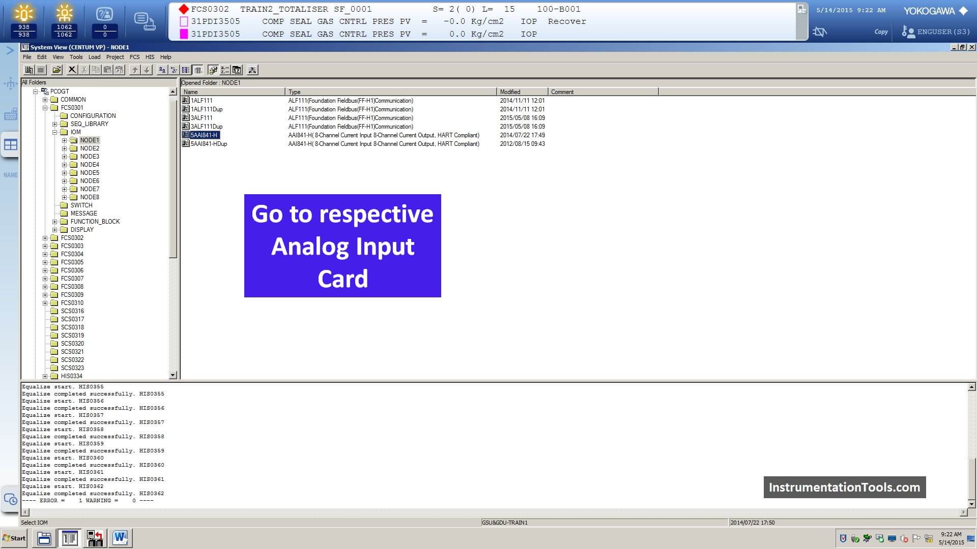
Step 4: Go to Analog Input Card
Next, select the analog input card (AAI841-H) and open it.
The location AI card details can be found in your plant nest loading list.
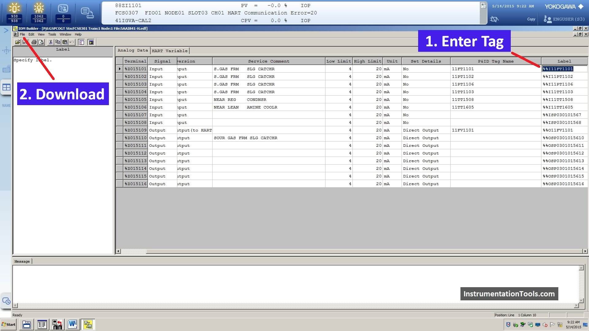
Step 5: Configure New Tag
Next, you have to add the tag name in the respective AI module channel.
Here the tag syntax is “%%I11FT1101”
Then go to file and download.
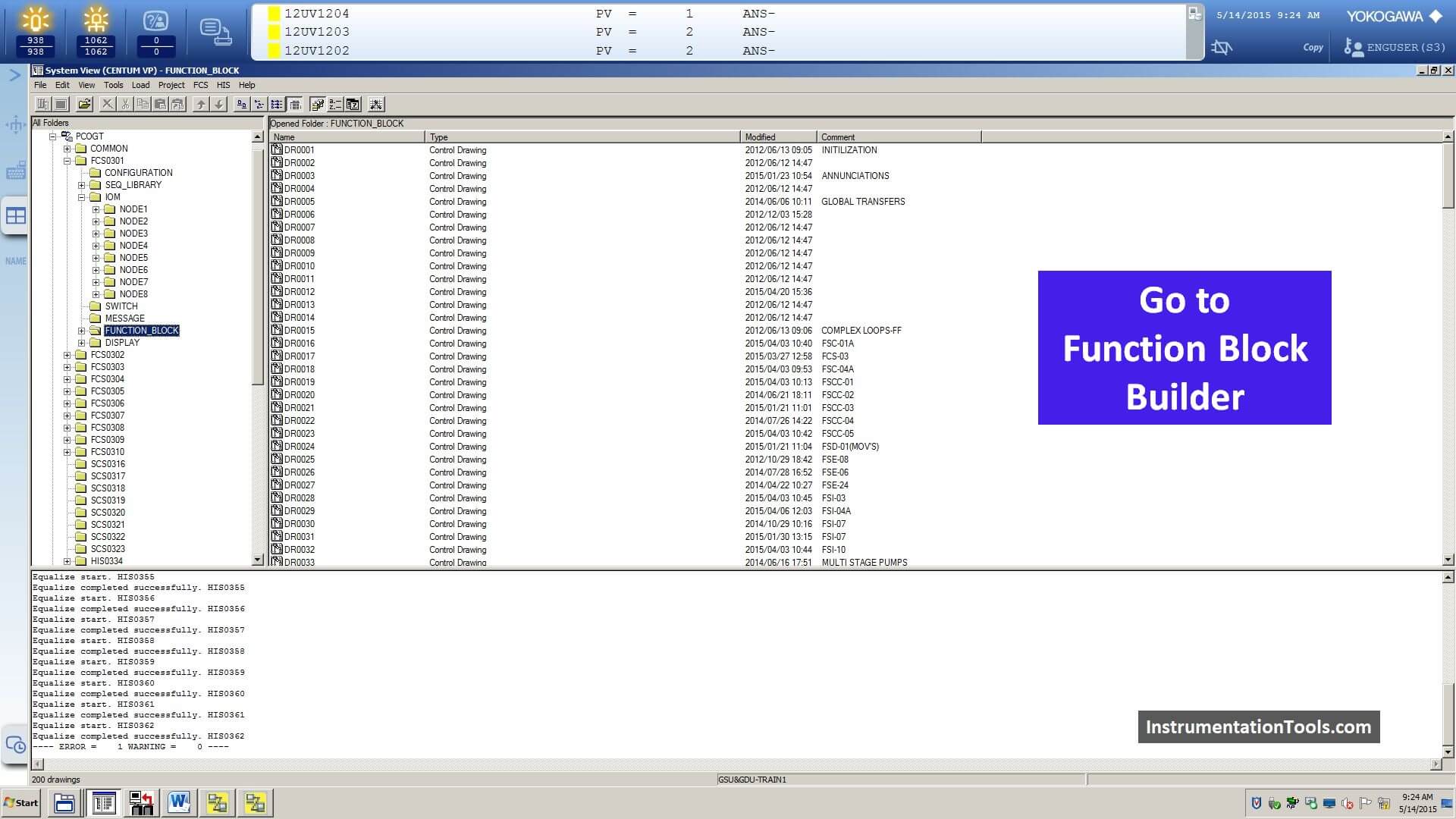
Step 6: Go to Function Block Builder
Now go function block builder for creating the faceplate of the new tag.
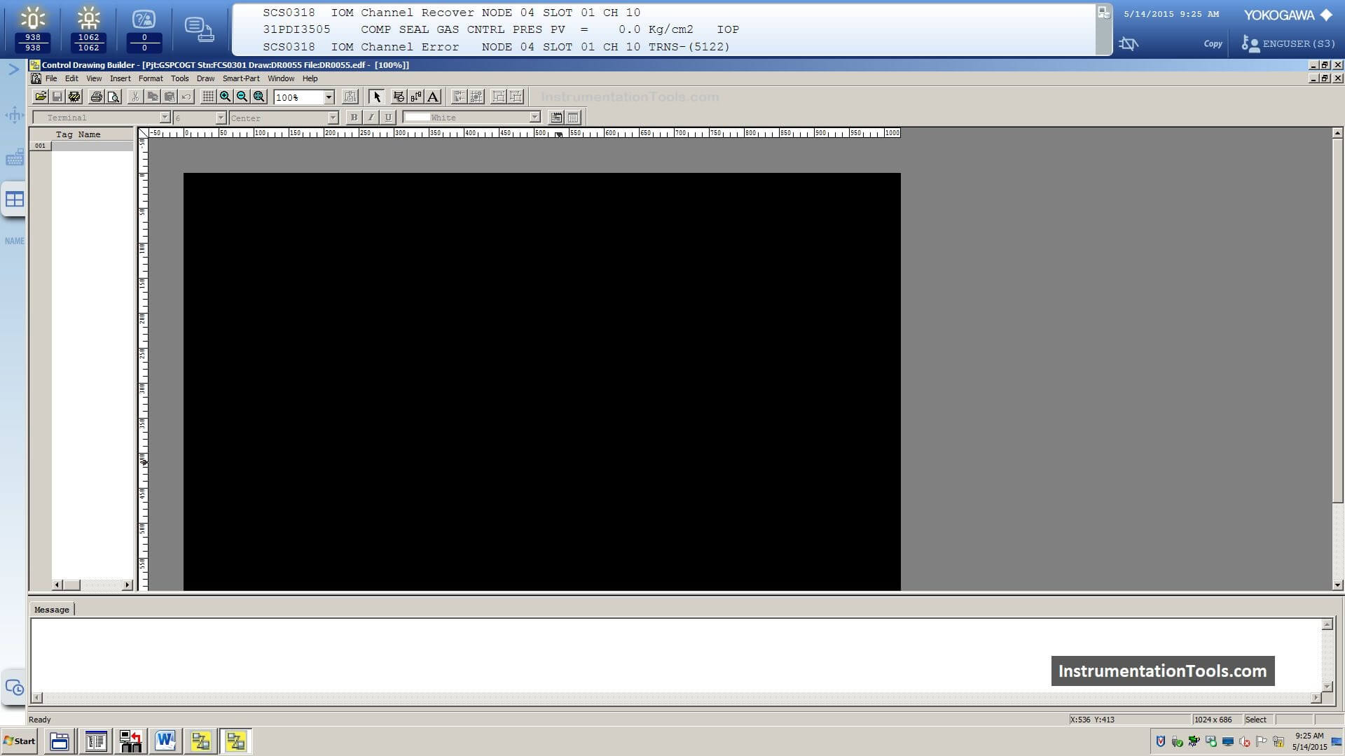
Step 7: Select the Control Drawing
Open the respective control drawing builder or choose any empty drawing.
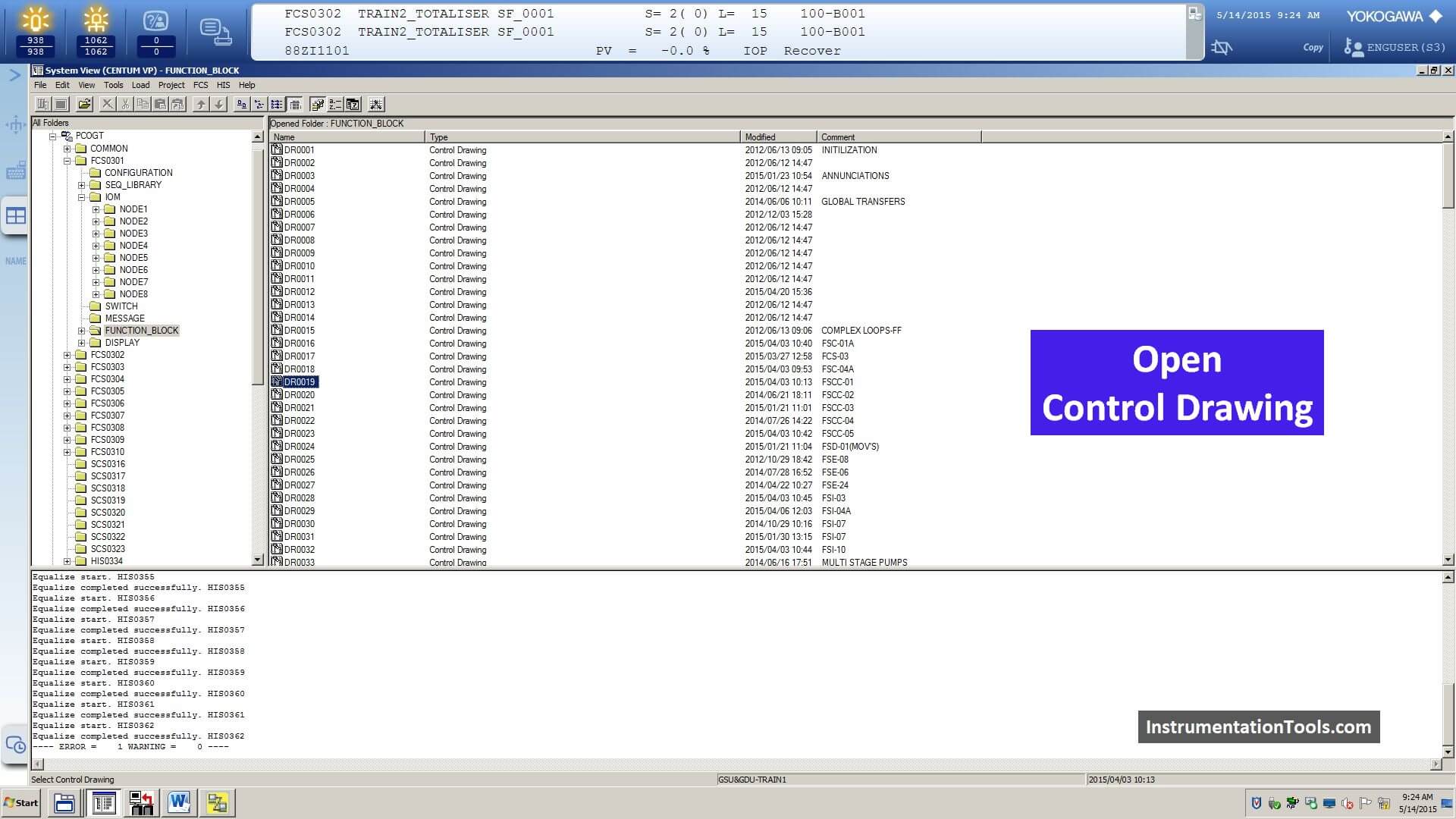
Step 8: Open the Control Drawing
Here, we selected a new control drawing.
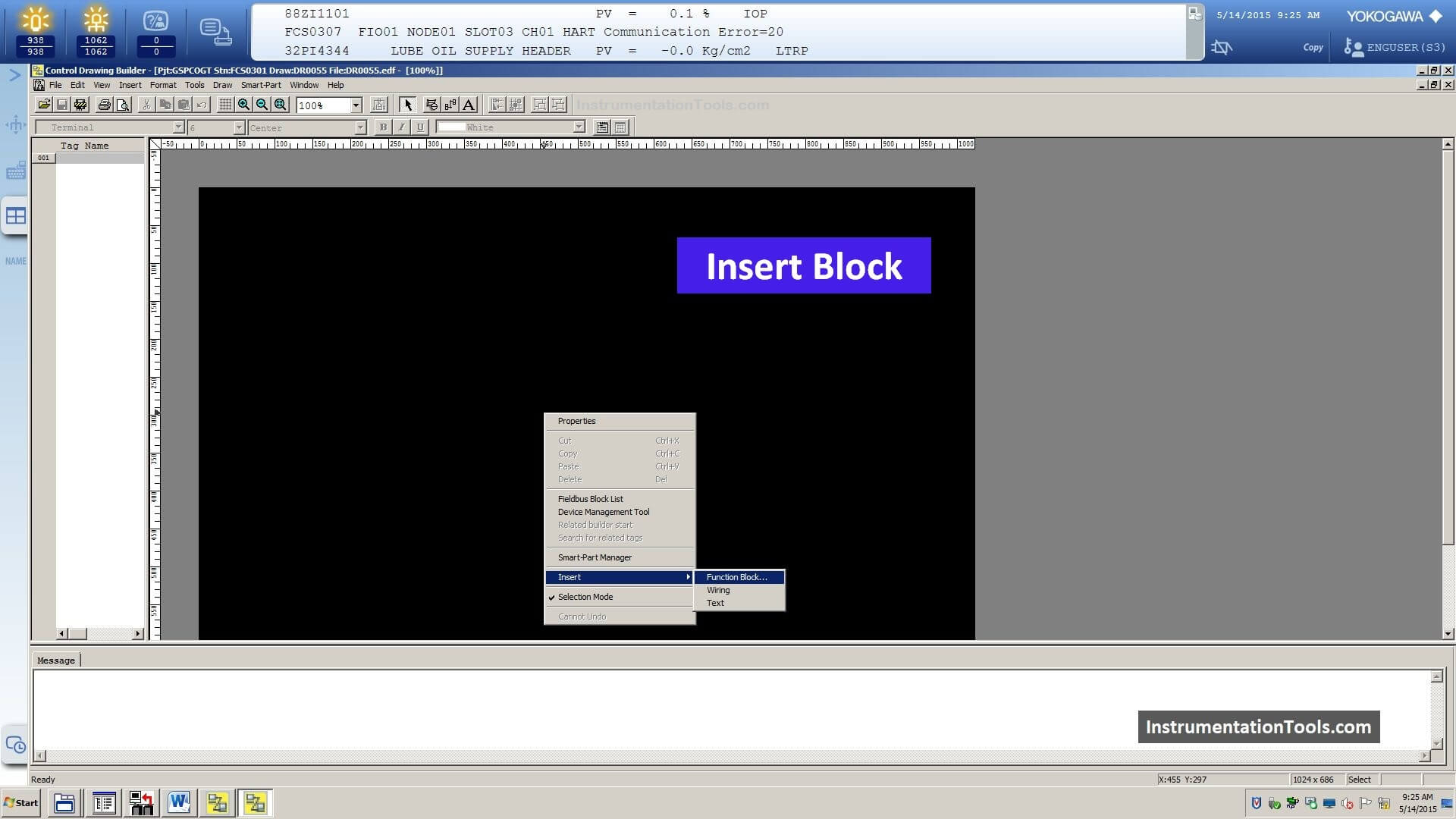
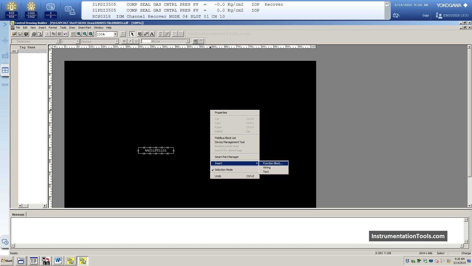
Step 9: Insert Function Block
Right-click on the screen and select the “Insert” option and then click on “Function Block”
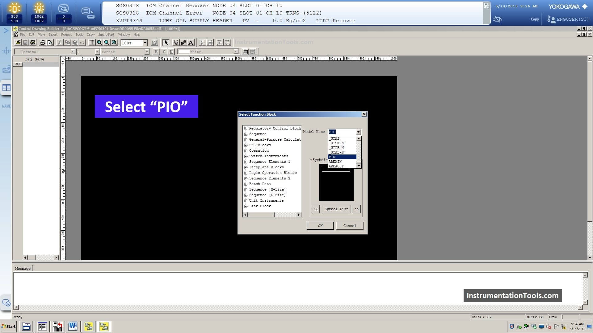
Step 10: Insert PIO Block
Here select the “PIO” block from the drop-down menu.
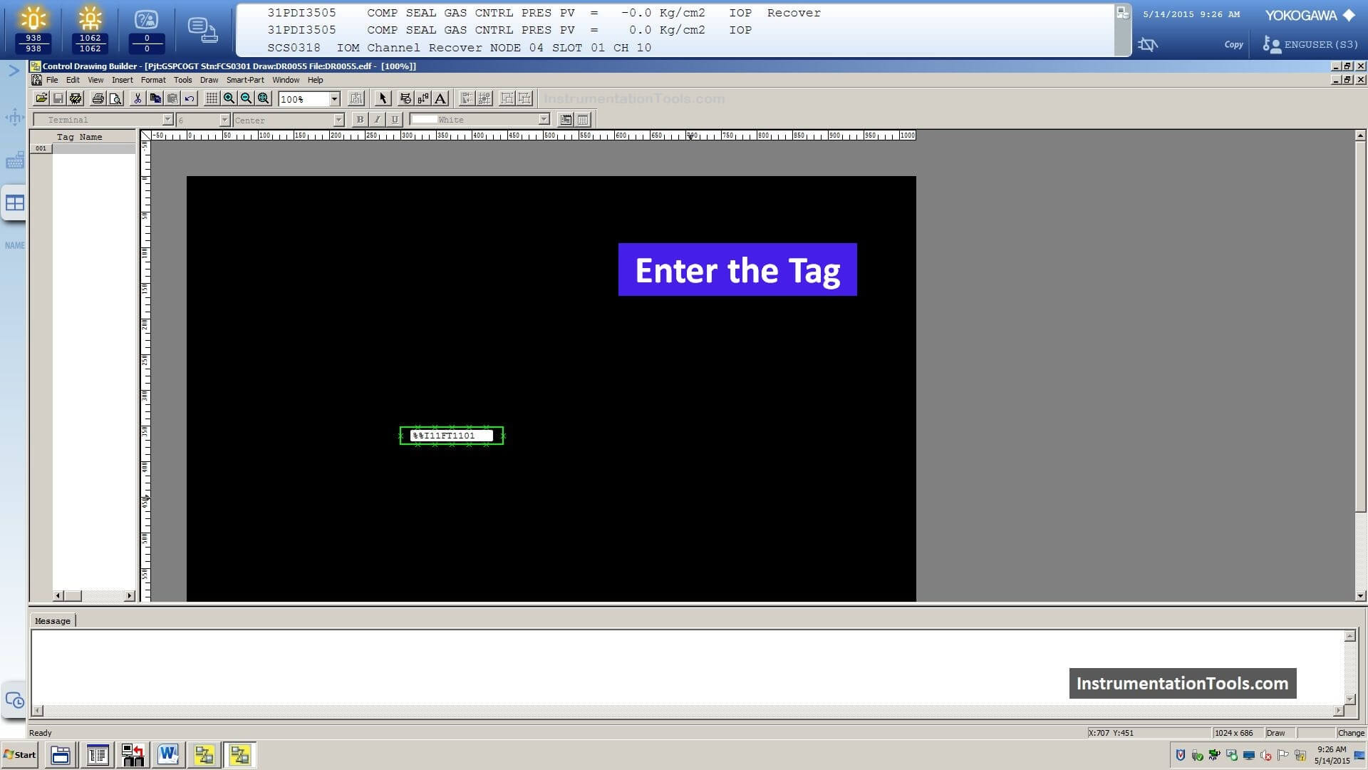
Step 11: Enter the New Tag in PIO Block
Now we have to enter the same tag name in the PIO block.
In this example, our tag is %%I11FT1101
Step 12: Right-click and select Function Block
Again we need another function block for the faceplate.
Step 13: Select PVI Block
Go to the menu and search for PVI block.
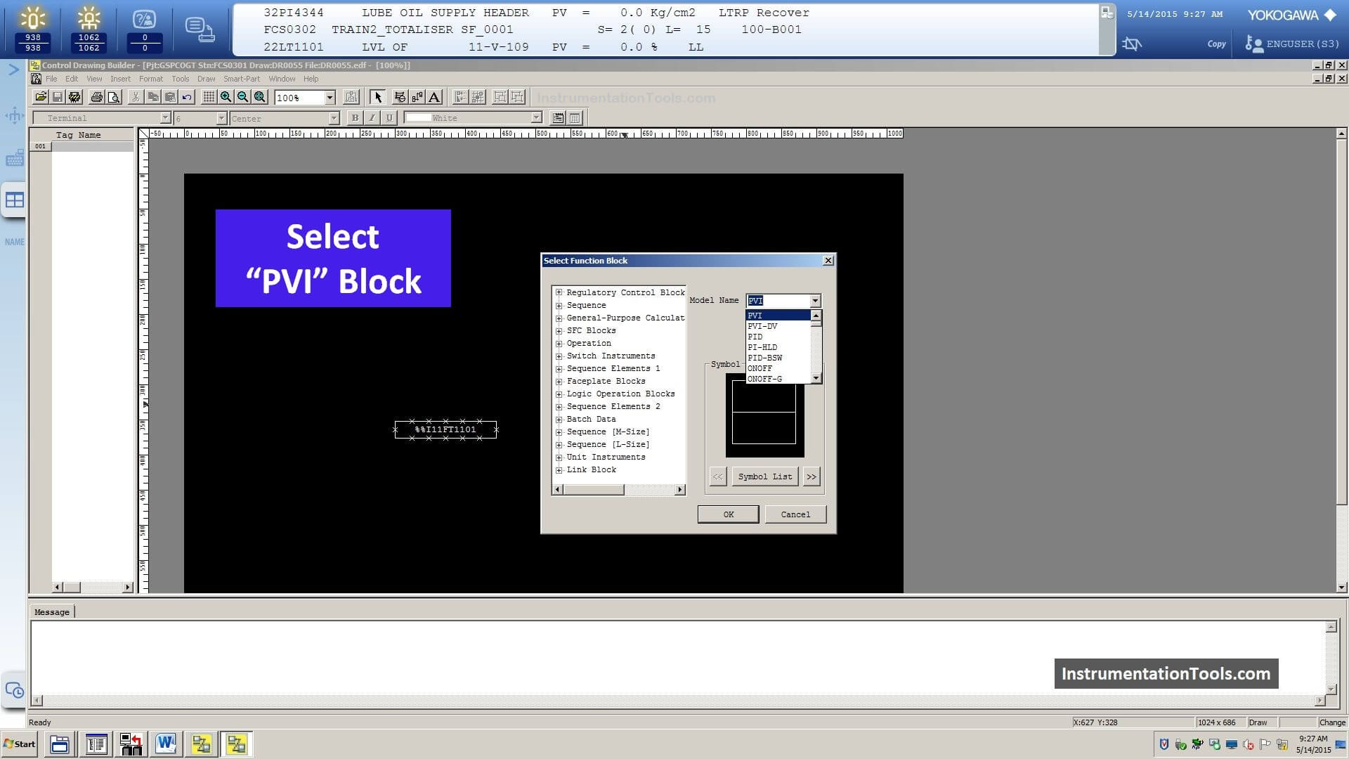
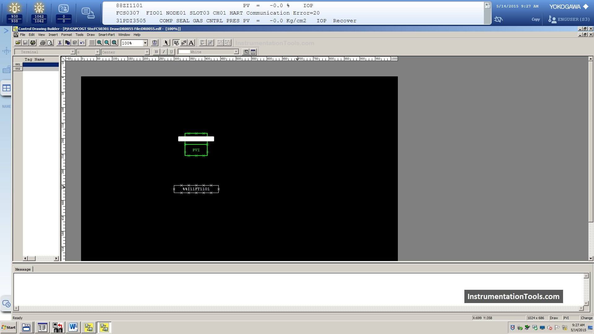
Step 14: Insert PVI Block
Now select PVI block (Input Indicator Block).
Each PVI block creates a faceplate for the tag after download.
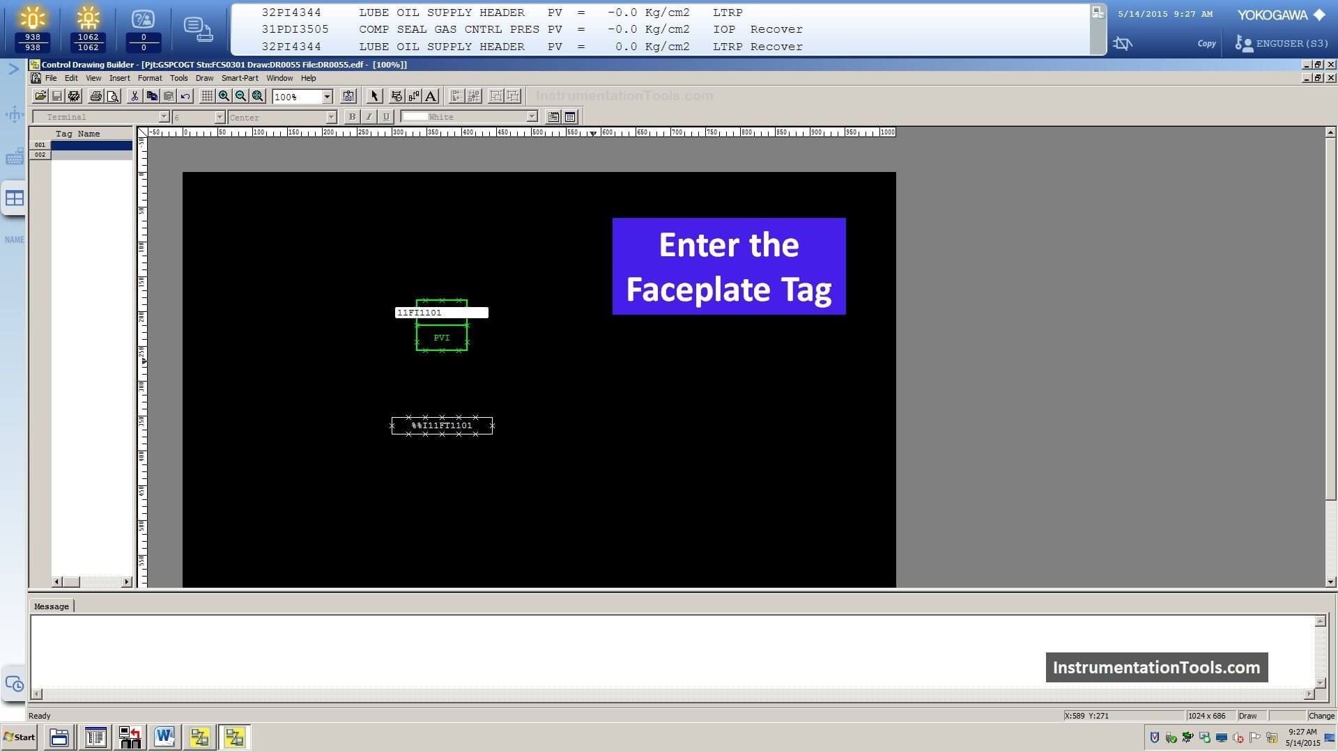
Step 15: Enter Faceplate Tag in PVI Block
Now we have to add a name for the PVI block.
In this example, we named the tag “11FI1101”.
This tag name is used for the faceplate.
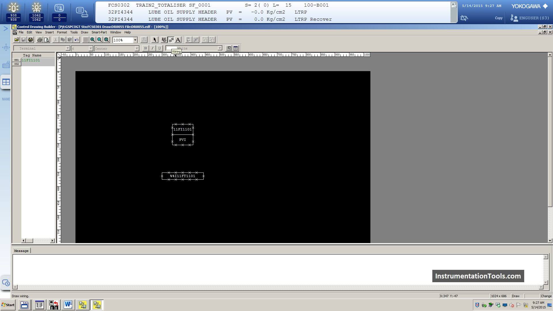
Step 16: PIO and PVI Blocks are Ready
Now both PIO and PVI blocks are created.
We need these two blocks when adding a new transmitter for monitoring purposes.
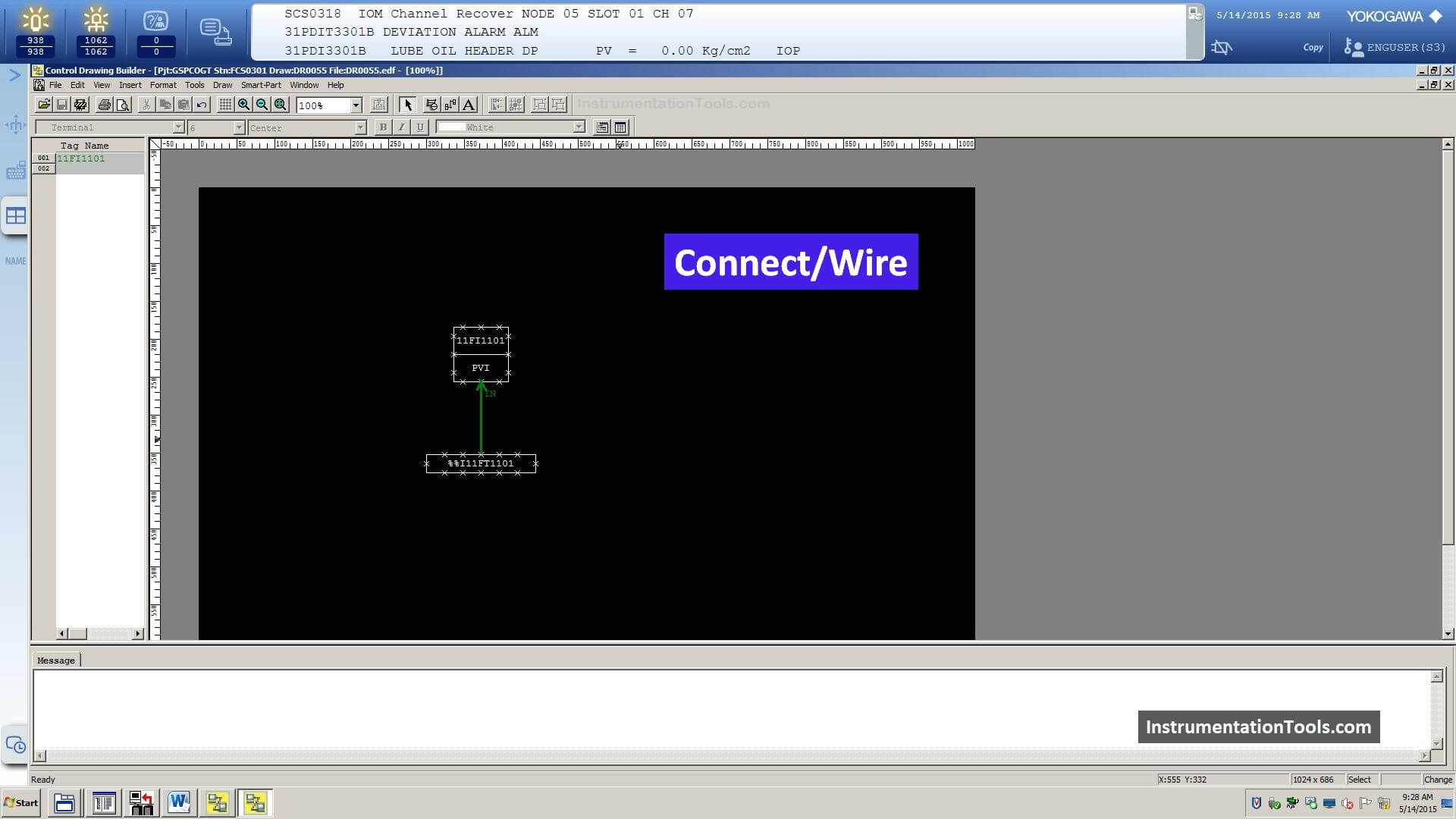
Step 17: Connect the PIO and PVI Blocks
Select the wire from the top menu and connect the PIO and PVI blocks as shown in the below image.
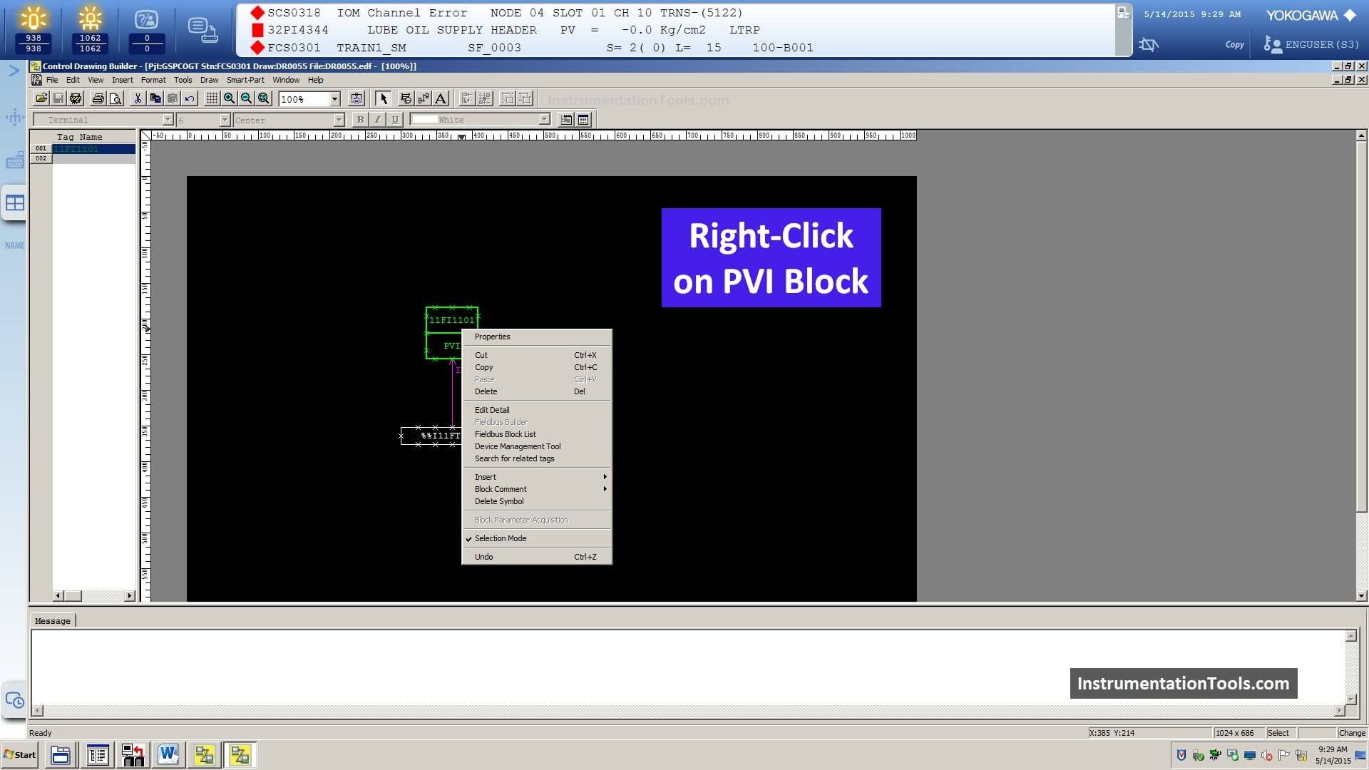
Step 18: Right-click on PVI Block
Now we have to add the details of the new transmitter in the DCS system.
Right-click on the PVI block.
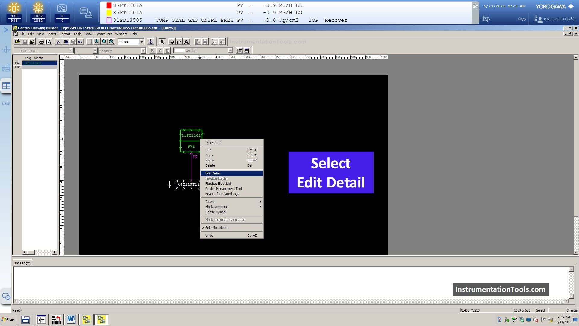
Step 19: Select Edit Detail
Select the “Edit Detail” option.
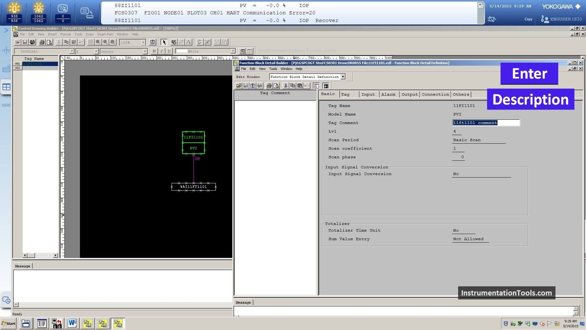
Step 20: Enter Transmitter (Tag) Description
Now a new window will be opened and it is called “Function Block Detail Builder”.
In this window, you can find different tabs like Basic, Tag, Input, Alarm, Output, Connection, Others.
In the basic tab, you can enter your faceplate description in the “Tag Comment” field.
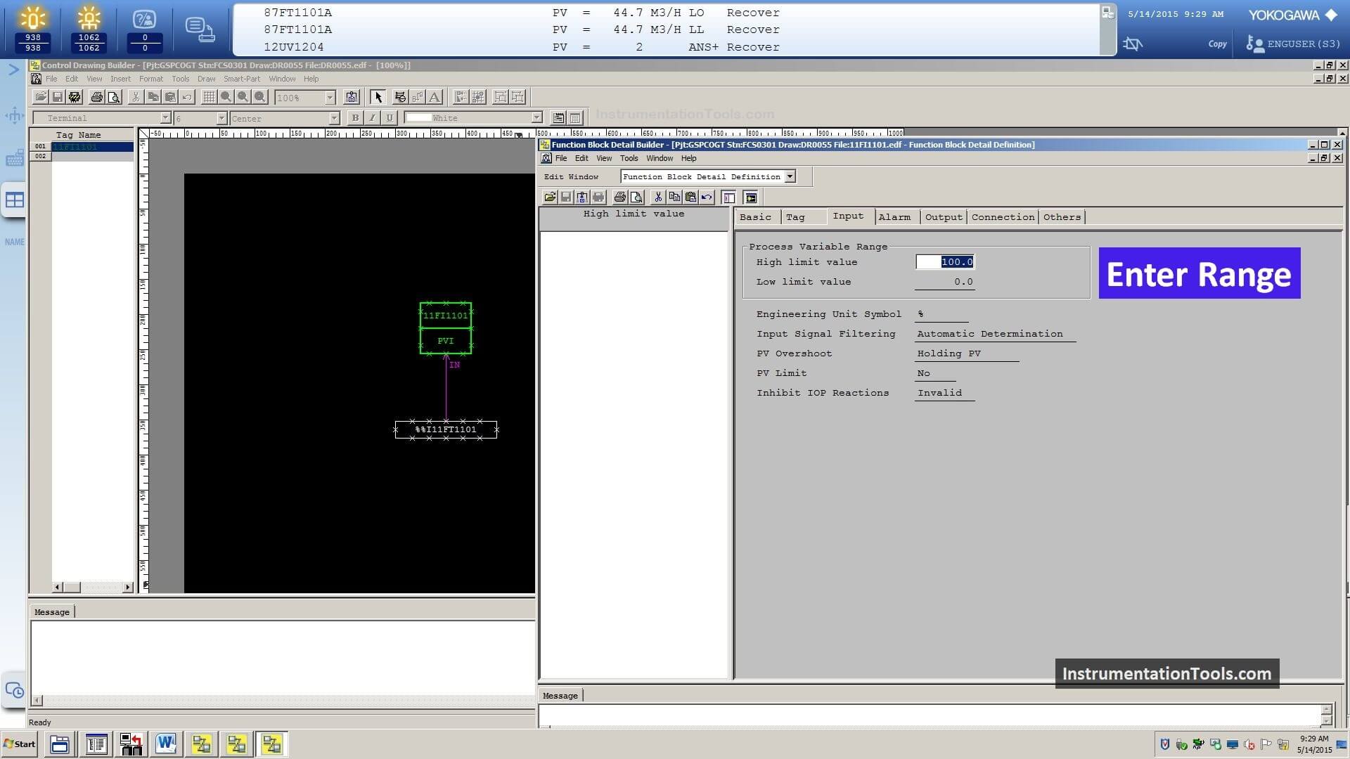
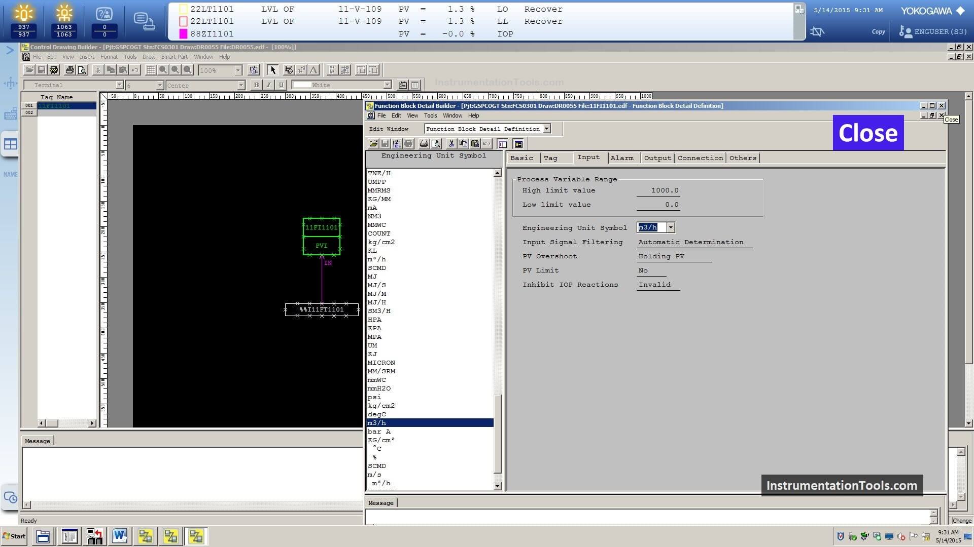
Step 21: Enter Transmitter (Tag) Range in DCS
Next, go to the “Input” tab. Here you can define the LRV and URV of your transmitter.
Fill the Low limit value (LRV) and High limit value (URV) as shown in the below image.
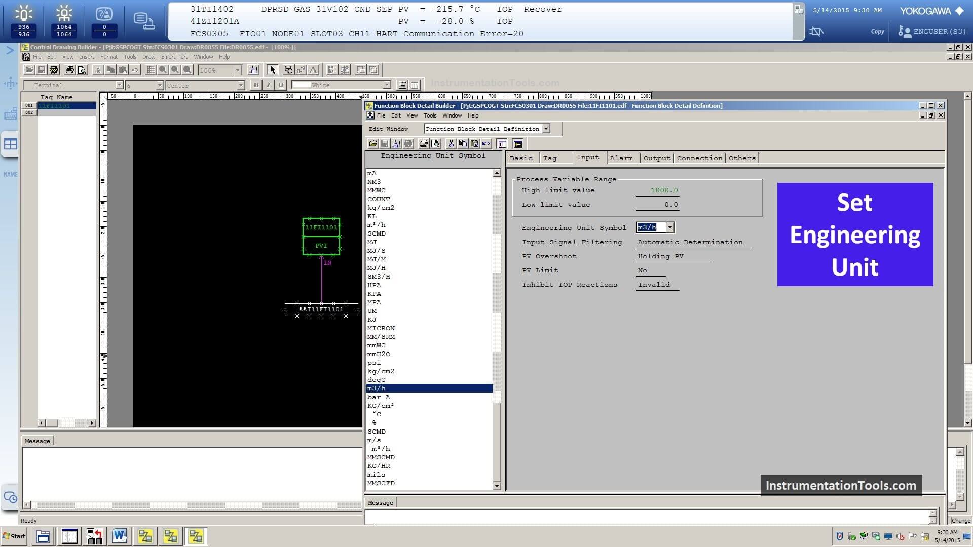
Step 22: Set Engineering Unit
In the Basic tab, you can define the required engineering unit for the new transmitter.
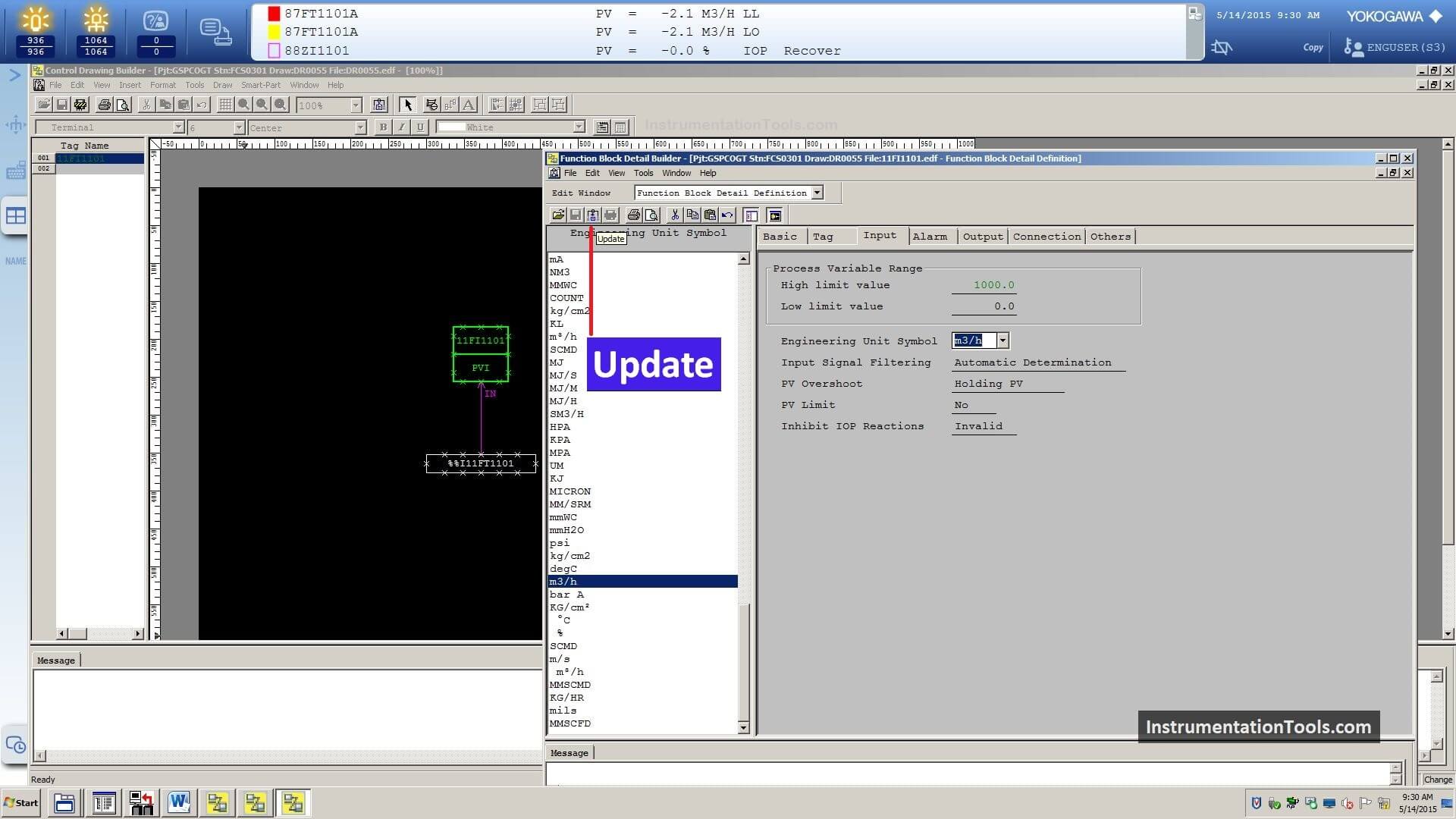
Step 23: Click Update button
Then click the update button
Step 24: Close Function Block Detail Builder
All settings are done, close the function block detail builder window.
Step 25: Go to File menu
Click on the File menu.
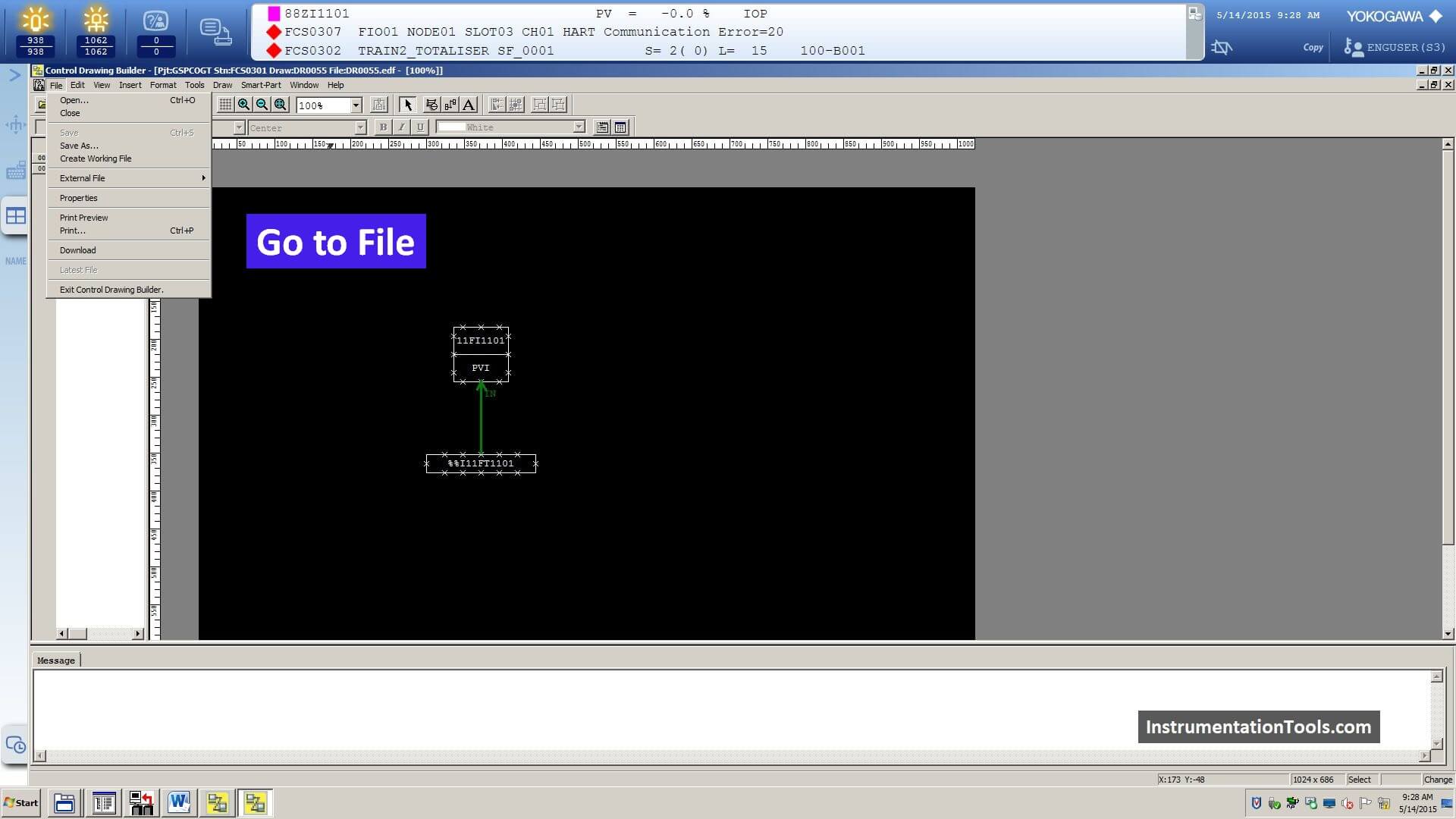
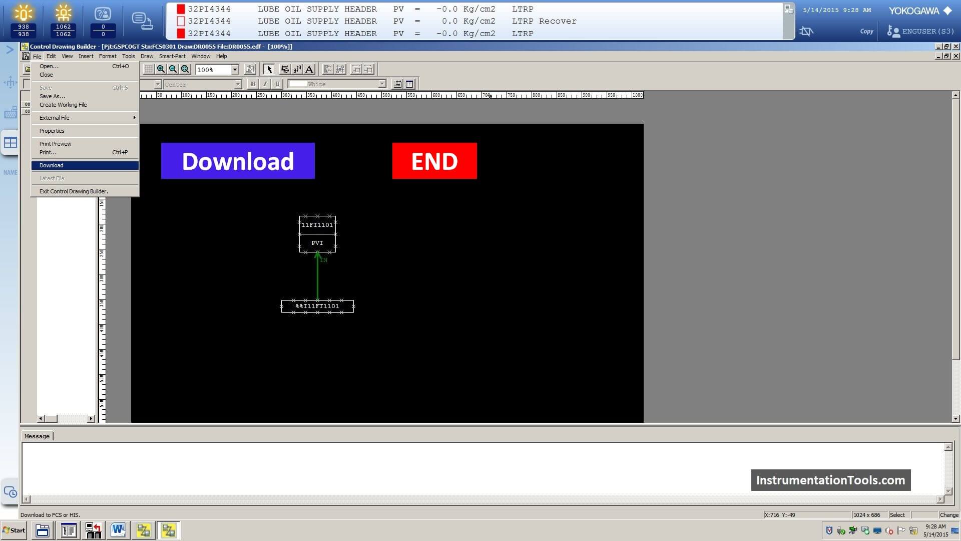
Step 6: Initiate Online Download
Select the “Download” Option.
Next, an online download will be started for this FCS. A pop-up confirmation window will appear and press ok.
Watch Video: Yokogawa DCS Offline Download
In this article, we discussed the basic settings required for the configuration of a transmitter in a DCS system.
We have many other features available like defining the alarms, displaying the transmitter value in graphics, creating trends for the new tag, etc. We will discuss these topics in upcoming articles.
Interest to add any further points? Share with us through below comments section.
If you liked this article, then please subscribe to our YouTube Channel for Instrumentation, Electrical, PLC, and SCADA video tutorials.
You can also follow us on Facebook and Twitter to receive daily updates.
Read Next:
- DCS Troubleshooting
- Commissioning of DCS System
- DCS Control System Spares
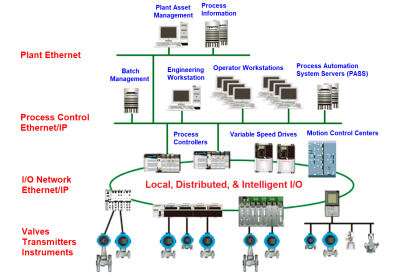
- Yokogawa DCS Architecture
- DCS System Layout


very helpful material please carry on your data is very perfectively managed.
I want to get basic knowledge of Dcs system.
Good work.
please provide DCS training course
GREAT STAFF. THANK YOU SO MUCH
Hi,
How can I monitor an Analog Input signal that described abow, monitor in HIS?
hi,
thank you for this great effort and great tutorial, I was wondering where to define the alarms treshold for this transmitter as I don’t see any place in PVI block for this purpose.
kind regards
1. PVI Block > Edit Properties
2. Open Faceplate > Tuning