Following steps shows procedure in commissioning a differential pressure (DP) transmitter for measuring water level in a pressurized closed tank.
In this article, we will discuss about a steam boiler remote level indicator setup and operating procedure of all valves related to the DP transmitter.
Firstly, refer to the manufacturer’s manual for setting DP transmitter parameters such as;
Measuring range, measured value in mA, % and display unit in pressure, process variable damping, specific output current in the event of an error/failure, zero/span, etc.
Configure the required parameters in the DP transmitter using HART communicator.
Follow this tutorial for configuring a transmitter using HART. Click Here
Commissioning a Differential Pressure Transmitter
DP transmitter is typically installed at a lower level than the pressure source (steam boiler) as shown in the diagram below.
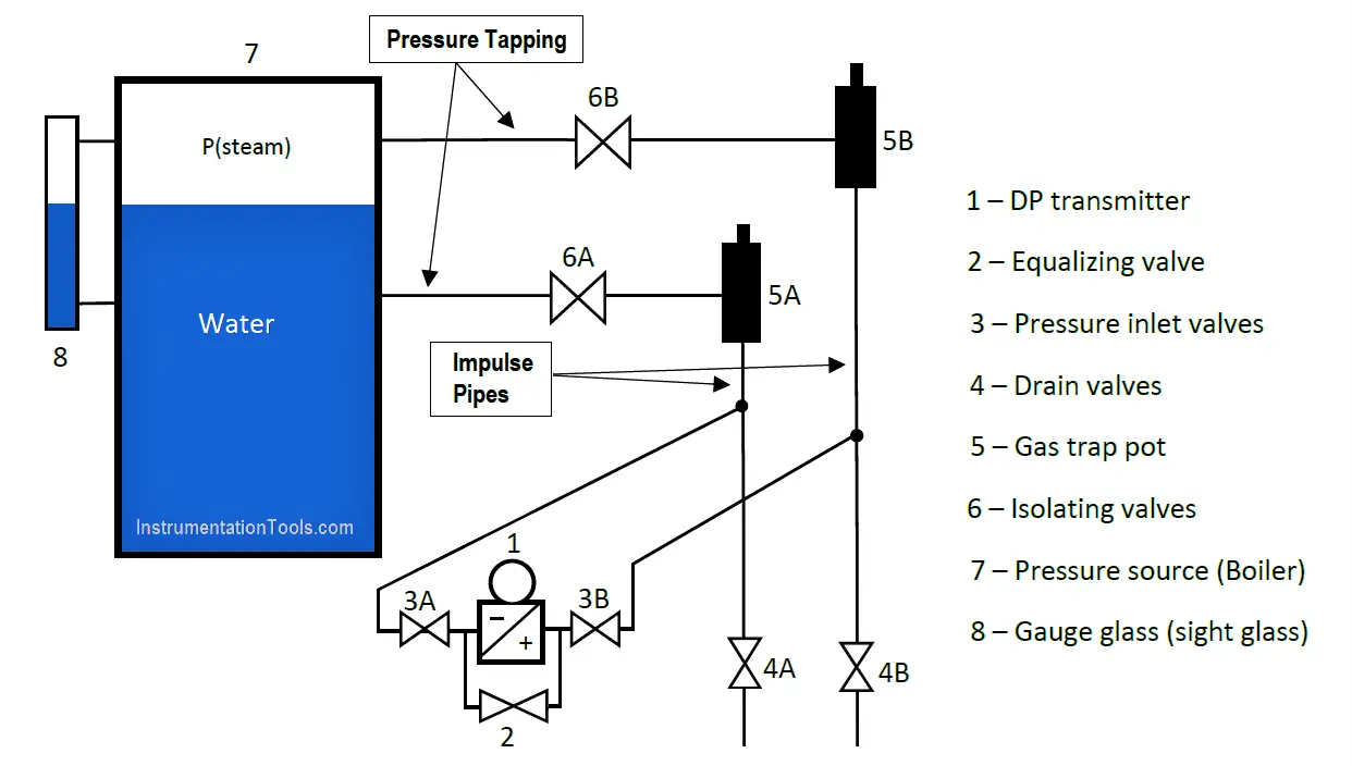
Secondly, the actual water level in the steam drum, referencing the level in the gauge glass, should be between negative and positive legs of the pressure tapping.
The water in the steam drum should be under steam pressure, and the valves operated slowly with some time delay in between.
Operating Procedure
The valves are operated in the following sequence:
STEP 1:
Initial setting – all valves are closed.
STEP 2:
Slowly open isolating valve (6A).
STEP 3:
Slightly open drain valve (4A) to purge the impulse line of air until only water escape. Shut the drain valve (4A).
STEP 4:
Slightly open vent plug on gas trap pot (5A) to purge air until only water escape.
Shut the vent plug.
STEP 5:
Slowly open pressure inlet valves (3A), (3B) and equalizing valve (2).
STEP 6:
Slightly open the vent plugs on DP transmitter to purge air until only water escape.
Shut the vent plug.
STEP 7:
Slightly drain valve (4B) to purge the impulse line of air until only water escape.
Shut drain valve (4B).
STEP 8:
Slightly open vent plug on gas trap pot (5B) to purge air until only water escape.
Shut the vent plug.
NOTE: At this point, both sides of the DP transmitter are exposed to the same pressure. Check zero point (4mA) against start of scale of the DP transmitter and correct if necessary using HART.
STEP 9:
Close the equalizing valve (2).
STEP 10:
Slowly open isolating valve (6B).
After a while, compare the water level in the gauge glass with the DP transmitter current output and/or remote meter/HMI level indication, both level gauge and transmitter must show same readings because both has same tapping points.
Author: Kweku A. Hagan, TMIET
If you liked this article, then please subscribe to our YouTube Channel for Instrumentation, Electrical, PLC, and SCADA video tutorials.
You can also follow us on Facebook and Twitter to receive daily updates.
Read Next:


Thank you Kweku.
Please include the detailed calibration procedure using the HART communicator.
How to calculate the LRV and URV of the transmitter?
Please adds Zero and SPan calibration procedures.
Thanks
Alright Vasu, this article focused on valves set up.
Sir why this sequence needs to be followed, any suitable explanation..
do we need to follow this step every day