This article covers the basics of split Range control application used for controlling more than one final control element in process control.
Split Range Control Application
Problem Description
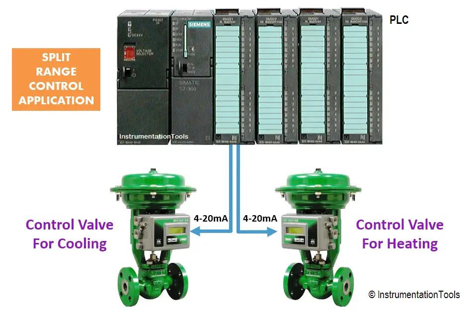
The products need to be heated and cooled depending on the temperature. There is one PID controller and we need to control 2 control valves.
Write a PLC program using ladder diagram language for this application.
Problem Diagram
Problem Solution
For this type of application, we need to use split range concept.
Split range concept mostly used when single controller is used to control multiple final control elements.
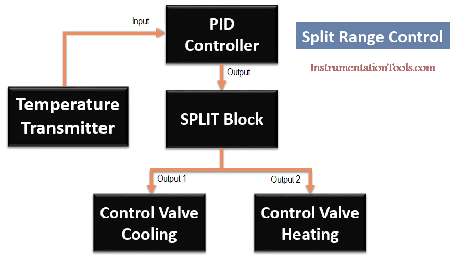
Here we considered temperature control application. Two control valves and one PID controller are used for temperature control.
Here consider one valve for cooling and another valve for heating process.
We will split controller output (here PID controller) for two different valves as shown in above figure.
In the diagram above, the 0% to 100% range of the PID controller output is connected to the SPLIT block and further control valves are connected to this SPLIT block as shown in above figure.
If the PID controller output is in between 0% to 50%, it is the cooling valve that is in operation. This valve is fully open when the controller output is 0% and fully closed when the controller output is 50%.
If the PID controller output is between in 50% to 100%, it is the heating valve that is in operation. At 50%, the heating valve starts to open and it is fully open at 100% of the controller output.
So, with PLC you can split both output using programming, hence you can connect 2 control valves with separate analog output of the PLC.
Also Read: Types of Split Range Control
List of Inputs and Outputs
Inputs List
- PID enable :- M61.0
- Manual enable :- M61.1
- PID reset :- M61.2
- Analog input form TC :- IW64
Outputs List
- Cooling control valve analog output :- QW96
- Heating control valve analog output :- QW98
M memory
- Set temperature :- MD500
- Actual temperature :- MD704
- PID output (%) :- MD758
- PID outputs for heating control valve :- MW762
- PID outputs for cooling control valve :- MW766
- PID state word :- MW770
- PID error word :- MD778
- PID enable input :- M61.0
- PID manual mode enable input :- M61.1
- PID controller reset :- M61.2
- PID high limit alarm :- M766.0
- PID low limit alarm :- M766.1
- PID input warning :- M766.2
PLC Program for split range control

Program Description
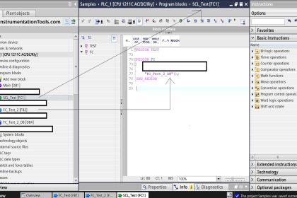
For this application, we used S7-1200 PLC and TIA portal software for programming.
Network 1
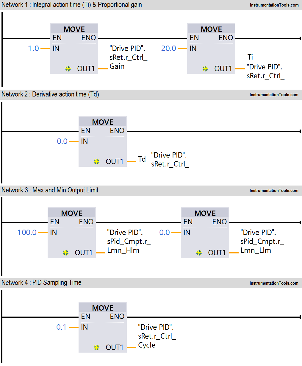
In network we configured standard parameters for PID function.
- “Drive PID”.sRet.r_Ctrl_Gain:- saved proportional gain or P gain for PID (1.0).
- “Drive PID”.sRet.r_Ctrl_Ti:-Saved integral time or I gain for PID (20s).
Network 2
“Drive PID”.sRet.r_Ctrl_Td:-Saved derivative time or D gain for PID (0s).
Network 3
Here we have taken temperature PID max output limit and minimum output limit. We have considered here max limit for PID output 100 and minimum limit is 0.
Network 4
Sampling time of the PID_Compact instruction r_Cycle is determined automatically and usually equivalent to the cycle time of the calling OB. Consider 0.1s for this application.
Network 5
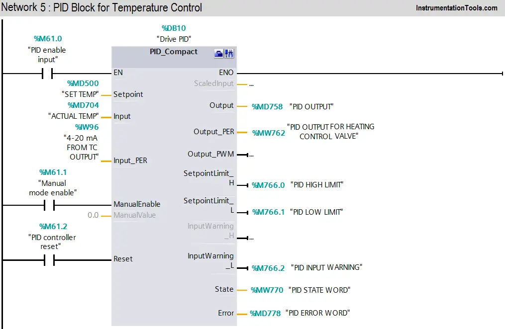
When PID enable (M61.0) is pressed PID block will be executed. As per SET point (MD500) it will generate output (0-27648) and according to actual temperature transmitter will give feedback (IW96) to PID.Manual enable (M61.1) is for manual operation and PID reset (M61.2) is for resetting the PID.
Network 6
Activate Mode after CPU restart If sb_RunModeByStartup = FALSE, the controller will remain inactive after a CPU startup.
Network 7
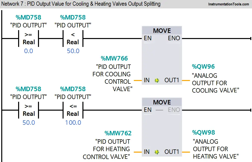
Here we used split range concept for output splitting. If PID output is between 0% to 50%, cooling valve will be working and if PID output is between 50% to 100%, heating valve will working.
Here we consider fail open valve for cooling and fail close valve for heating. Hence cooling valve is fully open when PID output is 0% and fully closed when PID output is 50%.
Similarly for heating valve, it will start to open when PID output is 50% and fully open when PID output is 100%.
Network 8
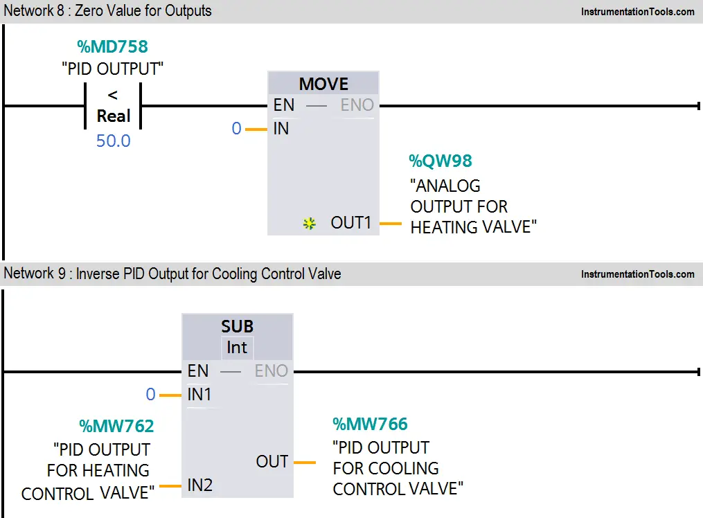
If PID output is less than 50%, zero valve will move in heating valve analog channel.
Network 9
Here we used inverse PID logic for fail to open valve.
Note:- Above application may be different from actual application. We can also make this application by using ready-made PID controllers and current to pressure converters.
This example is only for explanation purpose only. We can implement this logic in other PLC also. This is the simple split range control application used in industry, we can use this concept in other examples also.
All parameters and graphical representations considered in this example are for explanation purpose only, parameters or representation may be different in actual applications. Also all interlocks are not considered in the application.
If you liked this article, then please subscribe to our YouTube Channel for PLC and SCADA video tutorials.
You can also follow us on Facebook and Twitter to receive daily updates.
Read Next:
- PID Controller Selection
- Exclusive Control Valve Sequence
- How to tune a PID Controller?
- PID Controller Theory

Where do you write your MW766 for cooling control valve , if there is only on PID function?
Oh i see, network 9. Nice article btw.
Hi I learn a plc
Hello sir … Your every article is very usefull for us..can you make an article of program distribution and subroutine call up for AB PAC series
How split range control carried out in field without 2 Analog Outputs?
Krupali, We have implemented split range control with one analog output. we have split the air output from one I/P converter to two control valves.
For 0 to 50% o/p valve-1 will operate, 50-100 % valve-2 will operate( CV-2 is air to open and CV-1 is air to close) at 50% output both CVs are closed.
we have Calibrated CV-1 Positioner to be fully open 0%( 3 psi from I/P ) and fully open at 50% (9 Psi from I/P). same for CV-2 Positioner fully closed at 50% (9 psi from I/P) and fully open at 100% (15 Psi from I/P). For this to work we need to Calibrate CV Positioner with our suitable range. CV-1 is Cooling valve, CV-2 is heating valve.