Inst ToolsInst ToolsInst Tools
  • Courses
  • Automation
    • PLC
    • Control System
    • Safety System
    • Communication
    • Fire & Gas System
  • Instrumentation
    • Design
    • Pressure
    • Temperature
    • Flow
    • Level
    • Vibration
    • Analyzer
    • Control Valve
    • Switch
    • Calibration
    • Erection & Commissioning
  • Interview
    • Instrumentation
    • Electrical
    • Electronics
    • Practical
  • Q&A
    • Instrumentation
    • Control System
    • Electrical
    • Electronics
    • Analog Electronics
    • Digital Electronics
    • Power Electronics
    • Microprocessor
  • Request
Search
  • Books
  • Software
  • Projects
  • Process
  • Tools
  • Basics
  • Formula
  • Power Plant
  • Root Cause Analysis
  • Electrical Basics
  • Animation
  • Standards
  • 4-20 mA Course
  • Siemens PLC Course
Reading: Electrical Standards
Share
Notification Show More
Font ResizerAa
Inst ToolsInst Tools
Font ResizerAa
  • Courses
  • Design
  • PLC
  • Interview
  • Control System
Search
  • Courses
  • Automation
    • PLC
    • Control System
    • Safety System
    • Communication
    • Fire & Gas System
  • Instrumentation
    • Design
    • Pressure
    • Temperature
    • Flow
    • Level
    • Vibration
    • Analyzer
    • Control Valve
    • Switch
    • Calibration
    • Erection & Commissioning
  • Interview
    • Instrumentation
    • Electrical
    • Electronics
    • Practical
  • Q&A
    • Instrumentation
    • Control System
    • Electrical
    • Electronics
    • Analog Electronics
    • Digital Electronics
    • Power Electronics
    • Microprocessor
  • Request
Follow US
All rights reserved. Reproduction in whole or in part without written permission is prohibited.
Inst Tools > Blog > Calibration > Electrical Standards

Electrical Standards

Last updated: December 22, 2018 12:38 am
Editorial Staff
Calibration
No Comments
Share
3 Min Read
SHARE

Electrical calibration equipment – used to calibrate instruments measuring voltage, current, and resistance – must be periodically calibrated against higher-tier standards maintained by outside laboratories. In years past, instrument shops would often maintain their own standard cell batteries (often called Weston cells) as a primary voltage reference. These special-purpose batteries produced 1.0183 volts DC at room temperature with low uncertainty and drift, but were sensitive to vibration and non-trivial to actually use. Now, electronic voltage references have all but displaced standard cells in calibration shops and laboratories, but these references must be checked and adjusted for drift in order to maintain their NIST traceability.

One enormous benefit of electronic calibration references is that they are able to generate accurate currents and resistances in addition to voltage (and not just voltage at one fixed value, either!). Modern electronic references are digitally-controlled as well, which lends themselves well to automated testing in assembly-line environments, and/or programmed multi-point calibrations with automatic documentation of as-found and as-left calibration data.

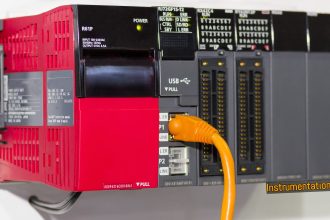
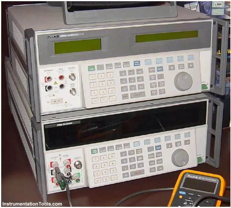
A photograph of some electronic calibration references appears here:

electronic calibration references

If a shop cannot afford one of these versatile references for benchtop calibration use, an acceptable alternative in some cases is to purchase a high-accuracy multimeter and equip the calibration bench with adjustable voltage, current, and resistance sources. These sources will be simultaneously connected to the high-accuracy multimeter and the instrument under test, and adjusted until the high-accuracy meter registers the desired value. The measurement shown by the instrument under test is then compared against the reference meter and adjusted until matching (to within the required tolerance).

The following illustration shows how a high-accuracy voltmeter could be used to calibrate a handheld voltmeter in this fashion:

high-accuracy voltmeter

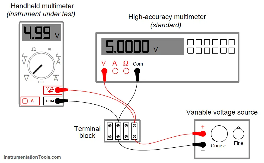
It should be noted that the variable voltage source shown in this test arrangement need not be sophisticated. It simply needs to be variable (to allow precise adjustment until the high-accuracy voltmeter registers the desired voltage value) and stable (so the adjustment will not drift appreciably over time). The accuracy of your calibration in the previous circuit originates not from the variable voltage source, but rather from the high-accuracy multimeter used as the calibration standard. It is the high-accuracy multimeter that serves as the calibration reference here, not the voltage source – it is the high-accuracy multimeter that functions as the standard.

Don't Miss Our Updates
Be the first to get exclusive content straight to your email.
We promise not to spam you. You can unsubscribe at any time.
Invalid email address
You've successfully subscribed !

Continue Reading

Solenoid Valve Functional Testing
Calibration MCQ – Terminology and Glossary Questions
Pressure Transmitter Calibration Procedure
Difference between Accuracy and Precision
Instrument Errors – Zero, Span, Linearity
Oxidation-Reduction Potential (ORP) Sensor Calibration Procedure
Share This Article
Facebook Whatsapp Whatsapp LinkedIn Copy Link
Share
Leave a Comment

Leave a Reply Cancel reply

Your email address will not be published. Required fields are marked *

Stay Connected

128.3kFollowersLike
69.1kFollowersFollow
210kSubscribersSubscribe
38kFollowersFollow

Categories

Explore More

Current to Pressure (I/P) Converter Calibration Procedure
Instrument Maintenance and Calibration System
Calibration Procedure of Weighing Balance and Common Mistakes
DeadWeight Tester Questions
Temperature Sensor calibration procedure
Step by Step Guide for Gas Flow Meter Calibration
How to Test a Pressure Gauge
DP Level Transmitter with Zero Suppression Calibration

Keep Learning

DP type Flow Transmitter Calibration

DP type Flow Transmitter Preventive Maintenance and Calibration

Calibration Standards

Practical Calibration Standards

Methods of Measurement

Methods of Measurement

Multimeter Digits

Multimeter – What Do Digits and Counts Mean?

Impulse Line Pressure Testing Procedure

Impulse Line Pressure Testing Procedure

Calibration Procedure of displacer type Level transmitter

Calibration of Displacer Level Transmitter

Magnehelic Gauge Calibration

Magnehelic Gauge Calibration

DP Diaphragm Capillary Seal Level instrument

DP Diaphragm Capillary Seal Level instrument Calibration Procedure

Learn More

Satellites Application in Agriculture

The Most Significant Developments in Satellite Technology

Electromagnetism Objective Questions and Answers

200+ Electromagnetism Objective Questions and Answers

How To Choose A Surge Protector?

How To Choose A Surge Protector?

Power Systems Questions & Answers

Power Systems MCQ Series 11

AC to DC Conversion with a Commutator

DC Machines Terminology

AND Logic in Bently Nevada Vibration System

AND Logic in Bently Nevada Vibration System

Change-of-Quantity Flow Measurement

Change-of-Quantity Flow Measurement

Core-Type Transformer

Transformer Theory of Operation

Menu

  • About
  • Privacy Policy
  • Copyright

Quick Links

  • Learn PLC
  • Helping Hand
  • Part Time Job

YouTube Subscribe

Follow US
All rights reserved. Reproduction in whole or in part without written permission is prohibited.
Welcome Back!

Sign in to your account

Username or Email Address
Password

Lost your password?