Inst ToolsInst ToolsInst Tools
  • Courses
  • Automation
    • PLC
    • Control System
    • Safety System
    • Communication
    • Fire & Gas System
  • Instrumentation
    • Design
    • Pressure
    • Temperature
    • Flow
    • Level
    • Vibration
    • Analyzer
    • Control Valve
    • Switch
    • Calibration
    • Erection & Commissioning
  • Interview
    • Instrumentation
    • Electrical
    • Electronics
    • Practical
  • Q&A
    • Instrumentation
    • Control System
    • Electrical
    • Electronics
    • Analog Electronics
    • Digital Electronics
    • Power Electronics
    • Microprocessor
  • Request
Search
  • Books
  • Software
  • Projects
  • Process
  • Tools
  • Basics
  • Formula
  • Power Plant
  • Root Cause Analysis
  • Electrical Basics
  • Animation
  • Standards
  • 4-20 mA Course
  • Siemens PLC Course
Reading: What is Ground, and importance of a Grounding System?
Share
Notification Show More
Font ResizerAa
Inst ToolsInst Tools
Font ResizerAa
  • Courses
  • Design
  • PLC
  • Interview
  • Control System
Search
  • Courses
  • Automation
    • PLC
    • Control System
    • Safety System
    • Communication
    • Fire & Gas System
  • Instrumentation
    • Design
    • Pressure
    • Temperature
    • Flow
    • Level
    • Vibration
    • Analyzer
    • Control Valve
    • Switch
    • Calibration
    • Erection & Commissioning
  • Interview
    • Instrumentation
    • Electrical
    • Electronics
    • Practical
  • Q&A
    • Instrumentation
    • Control System
    • Electrical
    • Electronics
    • Analog Electronics
    • Digital Electronics
    • Power Electronics
    • Microprocessor
  • Request
Follow US
All rights reserved. Reproduction in whole or in part without written permission is prohibited.
Inst Tools > Blog > Control Systems > What is Ground, and importance of a Grounding System?

What is Ground, and importance of a Grounding System?

Last updated: November 14, 2019 9:14 am
Editorial Staff
Control Systems
1 Comment
Share
5 Min Read
SHARE

Grounding is a very complex subject. The proper installation of grounding systems requires knowledge of soil characteristics, grounding conductor materials and compositions and grounding connections and terminations.

Contents
GroundingEarthingBondingWHY GROUND?Personnel SafetyEquipment and Building ProtectionElectrical Noise Reduction

Article 250 of the National Electrical Code (NEC) contains the general requirements for grounding and bonding of electrical installations in residential, commercial and industrial establishments. Many people often confuse or intermix the terms grounding, earthing and bonding.

To understand the simple terms:

Grounding

Grounding is connecting to a common point which is connected back to the electrical source. It may or may not be connected to the earth. An example where it is not connected to earth is the grounding of the electrical system inside an airplane.

Earthing

Earthing is a common term used outside the US and is the connection of the equipment and facilities grounds to Mother Earth. This is a must in a lightning protection system since earth is one of the terminals in a lightning stroke.

Bonding

Bonding is the permanent joining of metallic parts to form an electrically conductive path that will ensure electrical continuity and the capacity to conduct safely any current likely to be imposed.

WHY GROUND?

Importance of Grounding System


There are several important reasons why a grounding system should be installed. But the most important reason is to protect people! Secondary reasons include the protection of structures and equipment from unintentional contact with energized electrical lines. The grounding system must ensure maximum safety from electrical system faults and lightning.

A good grounding system must receive periodic inspection and maintenance, if needed, to retain its effectiveness. Continued or periodic maintenance is aided through adequate design, choice of materials and proper installation techniques to ensure that the grounding system resists deterioration or inadvertent destruction. Therefore, the minimal repair is needed to retain effectiveness throughout the life of the structure.

The grounding system serves three primary functions which are listed below.

Personnel Safety

Personnel safety is provided by low impedance grounding and bonding between metallic equipment, chassis, piping, and other conductive objects so that currents, due to faults or lightning, do not result in voltages sufficient to cause a shock hazard.

Proper grounding facilitates the operation of the overcurrent protective device protecting the circuit.

Equipment and Building Protection

Equipment and building protection is provided by low impedance grounding and bonding between electrical services, protective devices, equipment, and other conductive objects so that faults or lightning currents do not result in hazardous voltages within the building.

Also, the proper operation of overcurrent protective devices is frequently dependent upon low impedance fault current paths.

Electrical Noise Reduction

Proper grounding aids in electrical noise reduction and ensures:

  • The impedance between the signal ground points throughout the building is minimized.
  • The voltage potentials between interconnected equipment are minimized.
  • That the effects of electrical and magnetic field coupling are minimized.

Another function of the grounding system is to provide a reference for circuit conductors to stabilize their voltage to the ground during normal operation. The earth itself is not essential to provide a reference function. Another suitable conductive body may be used instead.

The function of a grounding electrode system and a ground terminal is to provide a system of conductors that ensures electrical contact with the earth. Two Fine Print Notes (FPN) that appear in Section 250-1 of the NEC provide a good summary of the reasons for grounding systems and circuit conductors and the conductive materials which enclose electrical conductors and equipment.

Reference: erico

Read Also:

  • Electrical Symbols
  • Compare Floating & Ground Voltage
  • PLC Objective Questions & Answers
  • What is Instrument Earthing?
  • How Cable Gland Works?
Don't Miss Our Updates
Be the first to get exclusive content straight to your email.
We promise not to spam you. You can unsubscribe at any time.
Invalid email address
You've successfully subscribed !

Continue Reading

PID Controller Action : Directing Acting & Reverse Acting
Process Control Instrumentation Glossary
Introduction to Modbus – Reading and Writing Data
Wiring Diagrams of PLC and DCS Systems – DI, DO, AI, AO
Serial Communication Error Checking Methods and Algorithms
The Idea Behind Shielded Cables
Share This Article
Facebook Whatsapp Whatsapp LinkedIn Copy Link
Share
1 Comment
  • Bikash Dutta says:
    October 13, 2019 at 10:03 am

    Good knowledge for every one

    Reply

Leave a Reply Cancel reply

Your email address will not be published. Required fields are marked *

Stay Connected

128.3kFollowersLike
69.1kFollowersFollow
210kSubscribersSubscribe
38kFollowersFollow

Categories

Explore More

Control Valve Split Range Example
Speed Control of Ship Electrical Motor Propulsion
Comparison of Control Loops – Open, Closed, Cascade, Feedforward, Ratio
What is the DDE Protocol?
Motor Control Center (MCC) Signal Interface Termination (SIT)
Inductive Coupling Effects
Network Switch Port Allocation Details
Instrumentation and Control (I&C) Design

Keep Learning

Industrial Automation Projects

Evaluating Industrial Automation Projects Return on investment (ROI)

Emergency Shutdown Button Installation (ESD)

Understanding Emergency Shutdown Button Installation (ESD)

High Integrity Pressure Protection System HIPPS

Overview of HIPPS System

Alarm Management System

What is Alarm Management System ?

Determine Voltage Drops at Respective Flow Rates

Determine Voltage Drops at Respective Flow Rates in Loop Diagram

What is a Network Switch?

Network Switch Requirement in SCADA and DCS Architecture

Two Out of Three Logic

Alarm and Trip Systems

Instrument Control Package (ICP)

Package Control and Safety Systems Implementation Methods

Learn More

Feedback Accelerometer System Objective Questions

Feedback Accelerometer System Objective Questions

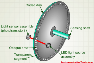
Encoder Principle

Encoder Working Principle

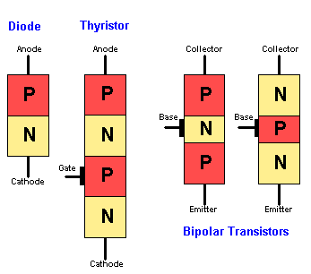
Basics of Thyristor

Basics of Thyristor

Example of Controlling the PLC Output using Push Buttons

Example of Controlling the PLC Output using Push Buttons

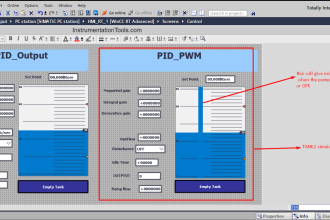
HMI Simulation for PID Controller

PID Controller Output Types – PID_PWM and PID_Output

BJT Amplifiers Interview Questions & Answers

BJT Amplifiers Interview Questions & Answers

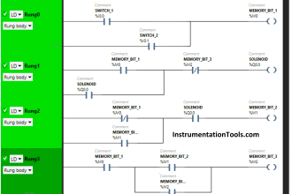
Create PLC Program based on Logic Circuit

Create PLC Program based on Logic Circuit

Digital Electronics MCQ

Karnaugh Map Objective Questions

Menu

  • About
  • Privacy Policy
  • Copyright

Quick Links

  • Learn PLC
  • Helping Hand
  • Part Time Job

YouTube Subscribe

Follow US
All rights reserved. Reproduction in whole or in part without written permission is prohibited.
Welcome Back!

Sign in to your account

Username or Email Address
Password

Lost your password?