“The ideal simplicity of the induction motor, its perfect reversibility, and other unique qualities render it eminently suitable for ship propulsion.”
– Inventor of induction motor scientist Nikola Tesla was an early proponent of electric propulsion for ships, wrote in Feb 1917.
Author: Jagabandhu Majumder FIE, Faculty IMTC Mumbai
Podded Drive Propulsion
Azipod, which stands for Azimuthing Podded Drive, represents a revolutionary approach to propulsion, made by ABB has become an industry standard for ice going vessels with its superior performance in the harshest of ice conditions, enabling vessels to cross the Northern Sea route independently. In late August 2019, Azipod propulsion has made history, driving a Norwegian Coast Guard icebreaker all the way to the North Pole.
This hull strength and podded electric propulsion technology unique ability to rotate the vessel 360 degrees with full torque and thrust in any direction with the combination Arctic’s double-acting ship (DAS) concept made all above achievement and the year-round journey possible, which gives also the container ships the capability of an icebreaking vessel and enables them to cut through 1.7 meters of level ice and more than 10 meters of ridged ice with considerably less installed power (13 megawatts) and lower energy consumption than conventional diesel-driven vessels of the same weight and hull design.

Figure 1 Double Acting LNG Carrier Propelling Heavy Ice Condition
Operating in temperatures as low as -50°C, a fleet of 15 Arc7 ice-class LNG carriers carrying liquid cargo are generally referred to as double-acting tankers with azimuth pod propulsion developed the concept for oil transportation between the Russian Arctic and Europe and the first double-acting tanker is a type of icebreaking ship designed to run ahead in open water and thin ice, but turn around and proceed astern in heavy ice conditions. In this way, the ship can operate independently in severe ice conditions without icebreaker assistance but retain better open-water performance than traditional icebreaking vessels
The first-ever cargo vessel to sail from Murmansk to Shanghai via the Northern Sea Route – without the assistance of icebreakers – recently completed its maiden crossing, cutting a 65-day journey on the return leg down to 19 days
There are mainly two manufactures of the pod propulsion system. ABB is the biggest producer and has two types of pod-types, Azipod (5-30 MW) and Compact (0.4-5 MW). Rolls-Royce (RR) is the second biggest company on the market, producing a pod called Mermaid (5-25 MW).
The latest Azipod M series is equipped with ABB’s fourth-generation permanent magnet motors that draw on proven Azipod propulsion technologies and have been refined to further increase power and maximize efficiency. The design simplicity of the system provides increased robustness and reliability, at the same time allowing for ease of maintenance.
Pod propulsion is a type of azimuth propulsion fitted in the place of the conventional propeller which is the combination of steering and propeller system consisting of an integrated electric motor installed in a pod that directly drives a fixed-pitch propeller.
The Pod assembly submerged outside the ship hull, installed in a gondola under the stern of the ship, having a short shaft line comprised of propeller, seals, bearings, and shaft, and the AC motor.
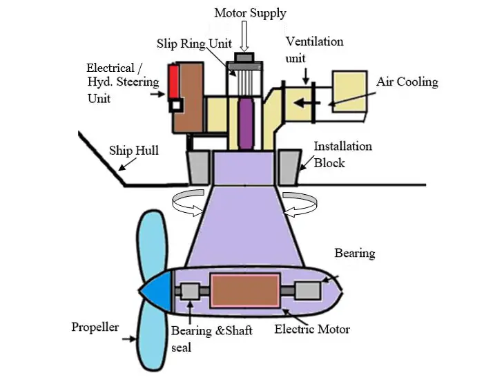
Figure 2 Parts of Pod Propulsion System
The steering module contains mechanical components include electric/ hydraulic steering motors, slewing transmission, slewing bearing, and slewing sealing that enables the steering function of the Azipod. The steering mechanics are connected to the ship with a mounting block.
Each Azipod steering module consists of four steering motors, each motor transmits power to the main gear rim through planetary gear and overload clutch which is in the shaft between the reduction gear and steering motor which protects the steering mechanics from external accidental loads also planetary gear and main gear in case of heavy overload.
The speed-controlled AC motor is controlled by a variable-frequency drive via the slip rings, provides full and smooth torque in either direction and at low speeds, thus giving excellent maneuverability, allows to steer large ships in confined spaces without the help of tugs. Dynamic positioning of the vessel for cruise ships is possible with an adequate number of pod propulsion units.
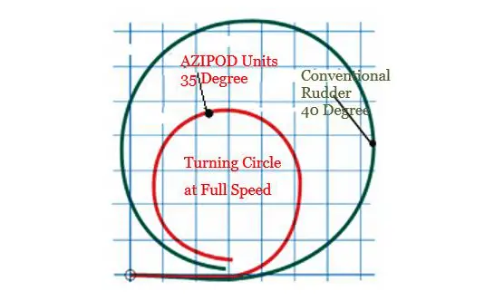
The more effective and safer turning capability of Azipod propulsion has been verified in the study by full-scale and full-speed turning circle tests between sister-ships MS Fantasy, with conventional propulsion, and MS Elation, with Azipod propulsion, which recorded 38 percent reduction in tactical diameter.
The pod propeller assembly revolves around a vertical axis can rotate 360 degrees ° and is used for steering the vessel, thus dispensing with the rudder and also easier for ships to have an ahead and astern to control the direction of motion without needing for reversing the prime mover motor or using a controllable pitch propeller.
Typical of the evolved POD propulsion is that the propeller pulls the ship as opposed to the conventional, less efficient pushing action. The crash-stop distance was also found to be substantially reduced as reversal can be performed either by reversing the propeller speed or by turning the Azipod unit through 180°.
The system eliminates the need for much heavy and bulky equipment required by conventional propulsion systems, including long shaft lines, reduction gears, controlled-pitch propellers, and transversal stern thrusters. Construction is made much easier, the maintenance load considerably less, and mechanical losses eliminated.
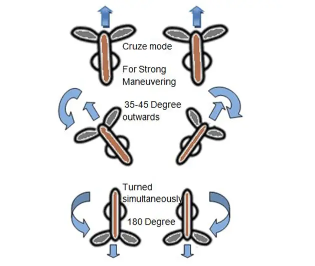
Figure 3 Various Maneuvering modes of Pod Propulsion
Advantages of POD Propulsion
- Up to 20% more energy efficiency with reduced fuel consumption and life cycle costs.
- Essential higher reliability and availability by the redundant configuration of the propulsion system.
- Saving time and money during construction;
- Environmentally friendly propulsion system Lower fuel consumption reduces emissions. A minimal need for lubricants reduces potential leaks. Podded propulsion also allows the use of biodegradable lubricants.
- Excellent maneuverability. Safe and maneuverable even the largest vessels can be maneuvered with decimeter accuracy. Narrow harbors can be entered quickly and safely.
- The vibration of the hull is reduced and there is no resonance effect of the propeller.
- The cavitation effect is reduced due to the fact that the diameter of the propeller is smaller,
- Economical operation as at reduced speed as the number of suppling generators can be matched according to the power demand.
Electrical Power System of Podded Propulsion
A single line diagram of electrical power systems of pod propulsion is shown in figure 4 which consists of sets of two pods each with exactly the same configuration independent of each other. Each motor has two stator windings with a frequency converter for redundancy.
A typical Pod Propulsion system has four main generators which are connected to the main switchboard, and the low voltage switchboard is supplied by ship service transformers. The main switchboard can be divided into two separate networks by means of the tie breakers to increase the redundancy of the power plant.
Pod propulsion power systems usually consist of High Voltage 11 KV / 6.6 KV gen-sets and, switchboards, Step down transformers, frequency converters are placed in the pod room in the ship, and synchronous motors in the pod for propulsion.
The slip ring unit is used to transfer the voltage and frequency-controlled power from the converter to the motor in the freely rotating pod.
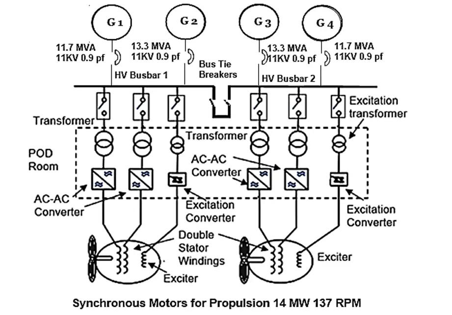
Figure 4 Typical single line diagram of the onboard Pod Propulsion system
Propulsion Motor and Excitation Components
Three types of propulsion motors are used: synchronous-, permanent magnet- and induction motors. The most common high-efficiency power factor 0.9 in high power range propulsion motor used is the synchronous motor (SM) because of its great power output.
SM rotor runs at synchronous speed, meaning that the rotor is spinning at the same rate as the synchronous speed of the rotating field of the stator winding. But the induction motor is making a great rise in smaller power podded propulsion.
Working Principle of Synchronous Motor (SM)
The construction of SM is similar to the Alternator. When the three-phase supply is given to the stator, the rotating magnetic field developed between the stator and rotor gap. the rotor is excited by the DC supply, induces the north and south poles on the rotor.
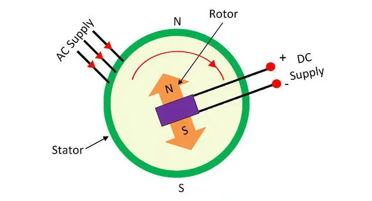
DC supply is switched on to magnetize the rotor when the rotor starts rotating around synchronous speed by starting with the help of an external prime mover or starting with the help of damper windings (SM runs like an induction motor ), or static frequency converter starting. The north and south poles of the rotor and the stator interlock each other.
Thus, the rotor starts rotating at the speed of the rotating magnetic field and the motor runs at the synchronous speed. The speed of the motor can only be changed by changing the frequency of the stator supply by the frequency converter.
Synchronous Motor for Propulsion
There are two methods to provide excitation for field windings, either by slip rings and brushes or by using a brushless excitation machine by which maintenances are greatly simplified, since there are no brushes and slip rings.
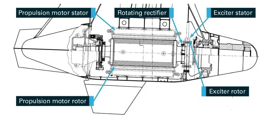
Figure 5 POD Synchronous Motor Brushless excitation of Rotor Windings
Brushless excitation system, DC current was supplied to the rotor of the propulsion motor from an exciter unit mounted on the same shaft as the main rotor. The AC generated in the exciter rotor was converted to DC via a rotating diode rectifier unit and supplied to the rotor of the propulsion motor.
Rotor Excitation by Brush & Slip ring
Applications for variable speed where very fast and accurate speed or torque control are required, the motor is generally equipped with brushes and a slip ring unit to allow excitation and control of the motor from the frequency converter.
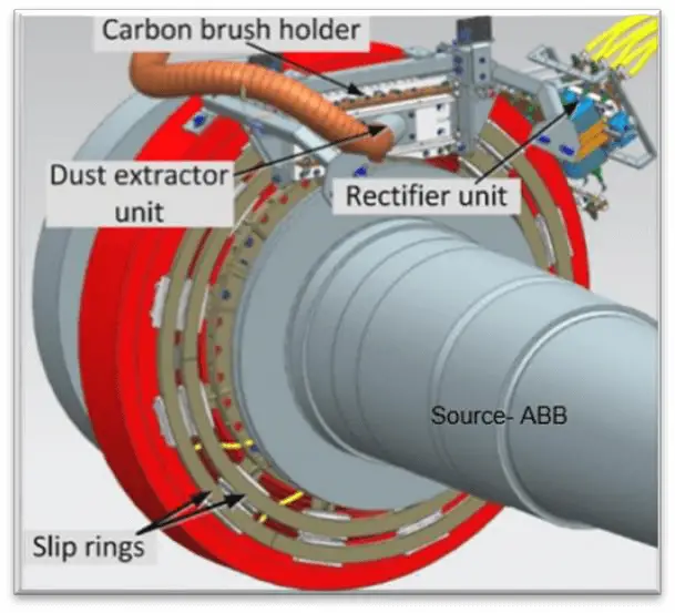
There are two slip rings of the face type located concentrically which are mounted on the motor shaft with access via removable inspection covers. The slip ring unit with brushes consisted of the installation of a slip ring assembly, diode bridge assembly, carbon brush assembly, and dust removal unit mounted on the existing exciter rotor and stator hub assembly.
The excitation of the rotor is supplied from an excitation transformer and excitation converter. The exciter converter is a three-phase converter with back-to-back thyristors (SCR) which can regulate the excitation of Propulsion SM as shown in figure 4.
The SM motor can be started with frequency converters by static frequency converter starting, and its speed can be precisely controlled. This is a great advantage when maneuvering through ports and berthing places.
Permanent Magnet Synchronous Motor (PMSM)
The permanent magnet synchronous motor (PMSM) used for high power application, which have a high electrical efficiency of 98%, good power factor, and has a robust and reliable design.
Rotor losses are minimized and also eliminates brushes and slip rings or brushless excitation components required for magnetizing the rotor.
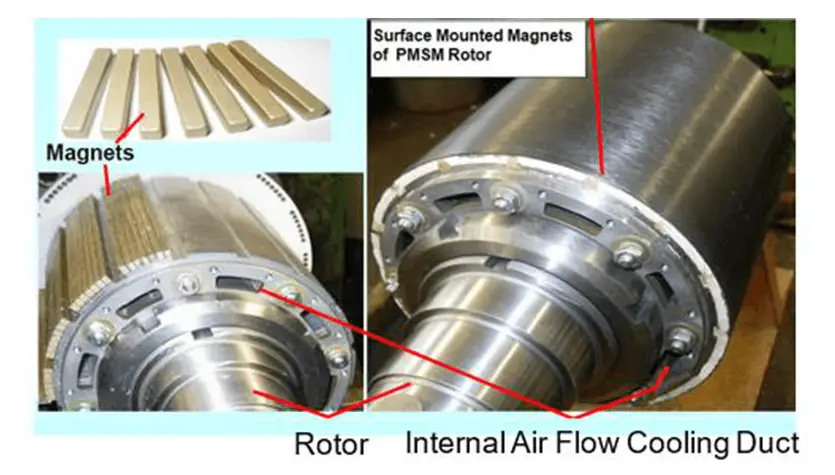
Figure 6 permanent magnet synchronous motor (PMSM)
Frequency Converter
The purpose of the frequency converter is to control the speed and torque of the motor by changing constant frequency into variable frequency and voltage. The technical development of semiconductors has been important and made many different designs of converters possible.
A converter has unwanted effects such as harmonic distortion that may disturb the system.
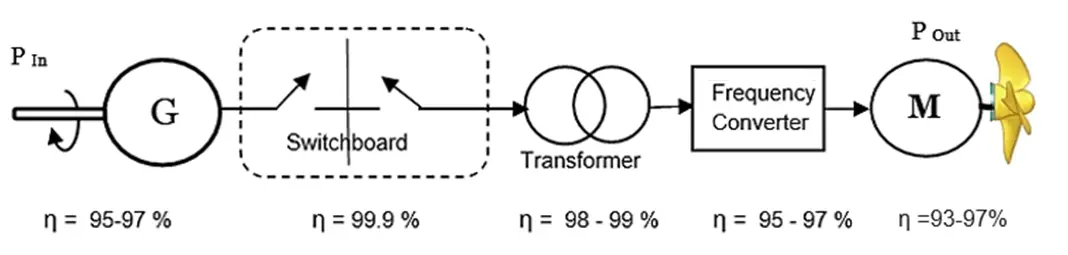
Figure: Power Flow and Efficiency of Pod Electric Propulsion Installation
The most commonly Frequency converter used in pod propulsion drive
Direct descendants of DC drive technology and use semiconductors component Silicon Controlled Rectifier (SCR) or “Thyristors”.
Thyristors are also known as a Silicon Controlled Rectifier (SCR) are turned on by applying firing pulse, small gate current when it is in forward bias and turns off when the anode current reaches zero.
The output voltage is varied by varying the firing or delay angle of gate pulse of SCR.
- Cyclo-converters (Cyclo) for AC motors, normally for synchronous motors
- Current source inverter type (CSI) converters for AC motors (synchronous motors)
The latest frequency converter type due to the technical development of power semiconductors differs from the two above by using high-speed controllable switches like Insulated Gate Bipolar Transistor (IGBT ) or Integrated Gate Controlled Thyristors, (IGCT). instead of thyristors.
This frequency converter is referred to as VSI-PWM as IGBT/IGCT can be turned on and off at high speed, so the output voltage can be controlled by Pulse-Width-Modulation (PWM). ❖ Voltage source inverter (VSI) type converters for AC motors, i.e. asynchronous, synchronous and permanent magnet synchronous motors.
A major difference between the three converters is their switching frequency, where the VSI has the highest output frequency at about 300Hz. The CSI has a maximum output frequency of approximately 120Hz while the cyclo only is able to give out 40% of the input frequency, 25Hz at 60Hz input.
Cycloconverter
A Cyclo-converters is an older technology AC drive, AC to AC frequency converters converts a constant voltage, constant frequency AC to another AC waveform of a lower frequency of a supply to the desired motor speed.
These are naturally commutated, direct frequency converters that use naturally commutated thyristors. The major advantage of the cyclo-converter is that it can produce high torque at a low speed with low torque pulsation and good dynamic behavior.
The disadvantage of the Cyclo-converter is the output frequency is limited to one-third of the input frequency for reasonable power output and efficiency.
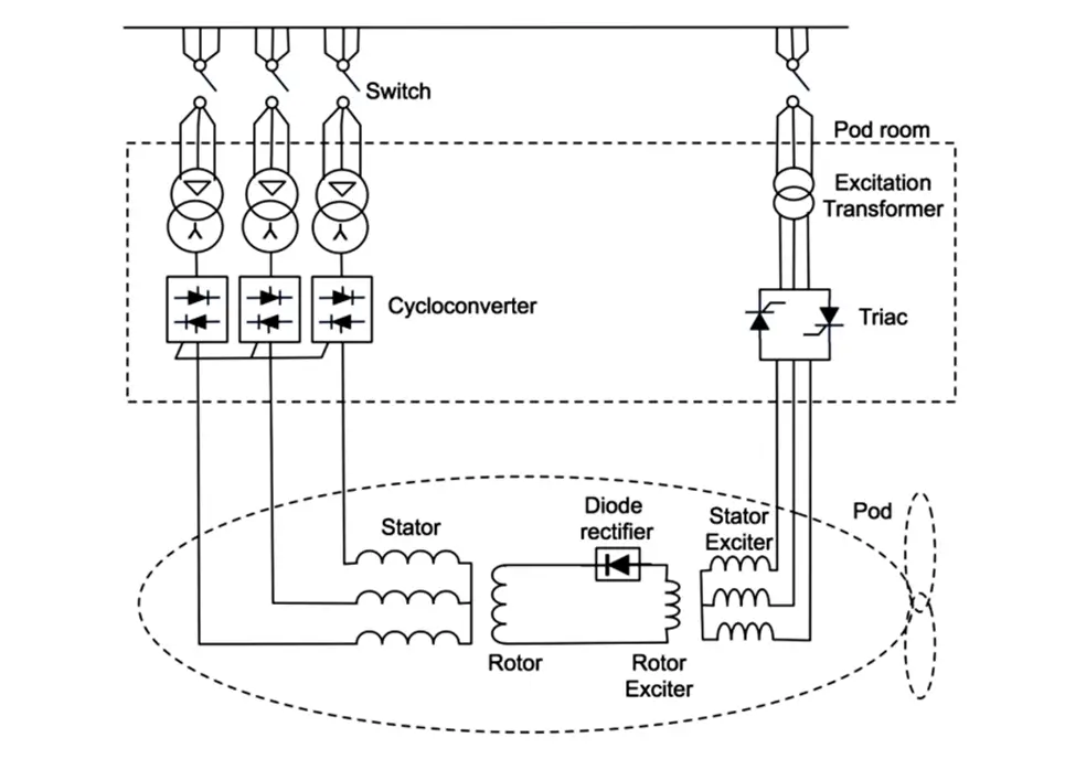
The Cyclo-converter consists of six groups of converter circuits where three groups are called positive bridge converter while the other three are negative bridge converter are connected in opposite direction (back to back), with both bridges being fed from interpose HV step-down transformers.
This reduces the motor voltage and its required insulation level while also providing additional line impedance to limit the size of prospective fault current and harmonic voltage distortion at the main supply bus-bar.
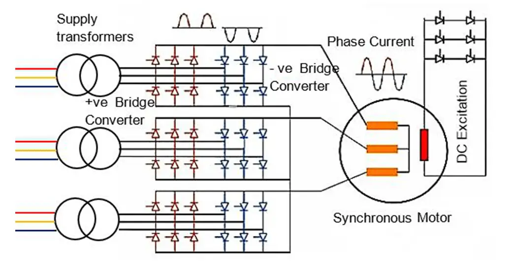
Figure 7 Cyclo-Converters for Speed Control of Synchronous Motor
During each positive half cycle, the positive group carries the current and during the negative half cycle, the negative group carries the current.
The duration for conduction of each group of thyristor determines the desired output frequency.
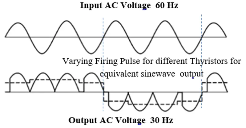
The average value of output voltage is varied by varying the firing or delay angle of SCRs conduction whereas the output frequency can be varied by changing the sequence of firing the SCRs.
Current Source Inverter (CSI) & Voltage Source Inverter (VSI)
The two most common types of inverters are the current source inverter (CSI) and the voltage source inverter (VSI). As their names imply, current source inverters are fed with constant current, while voltage source inverters are fed with constant voltage.
Consequently, the output of a CSI drive is adjustable, three-phase AC current, while a VSI drive produces three-phase AC voltage with adjustable magnitude and frequency. A key difference between CSI drives and VSI drives is their energy storage method.
CSI drives use inductive energy storage—that is, they use inductors in their DC link to store DC energy and regulate the current ripple between the converter and the inverter.
Conversely, VSI drives use capacitive storage, with capacitors in their DC link, which both stores and smooths the DC voltage for the inverter.
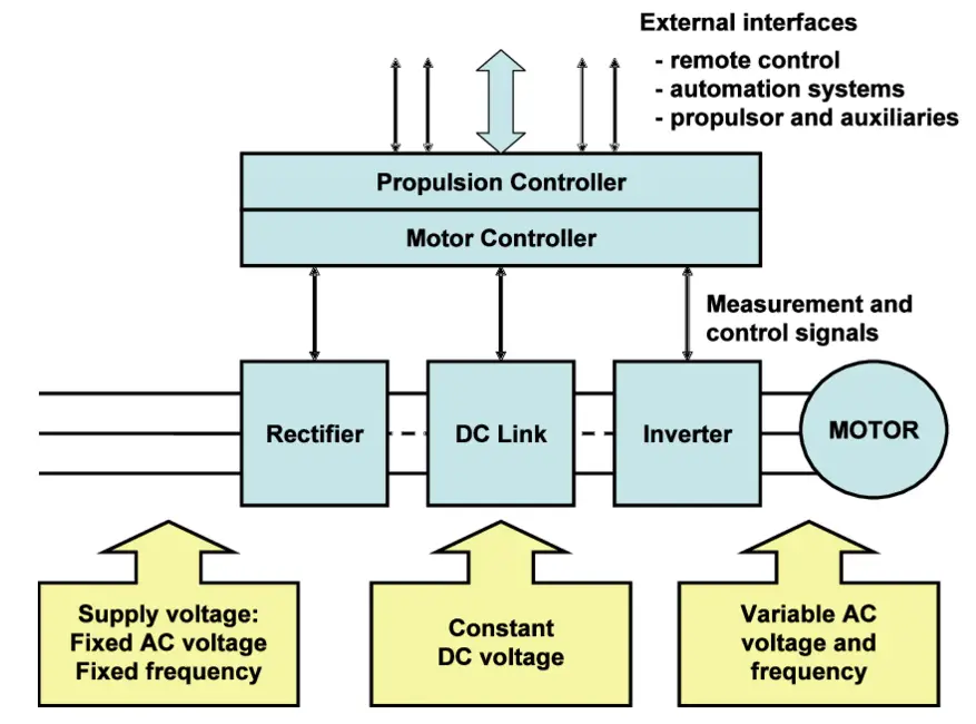
Figure 8 Variable Speed Control of Propulsion Motor for VSI and CSI type Frequency Converters
Current Source Inverter (Synchroconverter ) Working Principle
A synchro-converter has a controlled rectifier termed as source/line side converter and inverter stages termed as load side converter which both rely on natural turn-off or line commutation for the thyristors by the three-phase a.c. voltages at either end of the converter.
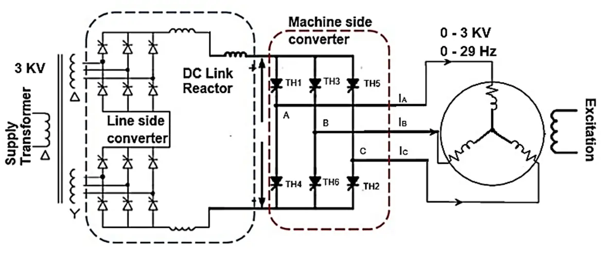
Figure 9 Synchronous Motor Drive employing a load commutated thyristor inverter (CSI)
The line /side converter is a 12-pulse line-commutated thyristor converter that takes power from the supply of constant frequency 60 Hz supply transformer star & delta multi secondary winding to give a 30-degree phase shift for 12 pulse rectification to reduce effect of harmonics due to switching phenomenon of the thyristor bridge.
Current flow in the line side converter is controlled by adjusting the firing angle of the input bridge thyristors offline side converter and by natural commutation of the AC supply line.
The DC link inductor or reactor is used to smooth the DC current which effectively turns the line side converter into a current source converter for the machine side converter.
As a result of the action of the link inductor L, such an inverter is frequently termed a naturally commutated current source inverter (CSI) occasionally referred to as a load commutated inverter (LCI) or Synchro.
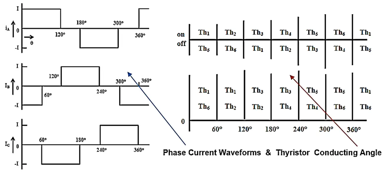
Figure 10 Phase Current Waveforms from Current Source Inverter
The thyristors of the output bridge (machine side converter) are fired in step with the rotation of the motor and act as an electronic commutator by controlling the thyristors of the inverter stage commutation of thyristor T1-T6, which are fired with a phase difference of 60º in the sequence of their number.
Each phase current waveform of phase difference 120 degrees of 6- step is obtained as shown in figure 10,, resulting in motor harmonics and torque ripples. The CSI requires a certain counter-induced voltage (EMF) from the motor to perform commutation. Hence, it is mainly used in synchronous motor drives in which the motor can be run with a capacitive power factor.
As the supply and machine bridges are identical and are both connected to a three-phase a.c. voltage source, their roles can be switched into reverse. This is useful to allow the regeneration of motor power back into the mains power supply which provides an electric braking torque during a crash stop of the ship.
Voltage Source Inverters (VSI) Working Principle
The voltage source inverter drives (VSI) use forced commutated high-speed power switches utilizing PWM (Pulse Width Modulated).
A wide range of forced commutated power switches are commonly used are Gate turn-off thyristor (GTO), Insulated Gate Bipolar Transistors – IGBTs, and Integrated Gate Commutated Thyristors – IGCTs.
Gate Turn-off Thyristor (GTO)
A Gate Turn-off Thyristor (GTO) is a special type of thyristor, which is a high power semiconductor device.
It was invented at General Electric GTOs, as opposed to normal thyristors, are fully controllable switches that can be turned on and off by their third lead, the Gate lead.
Insulated Gate Bipolar Transistors – IGBT
The insulated-gate bipolar transistor (IGBT) is a three-terminal power semiconductor device switching device that can be used for fast switching with high efficiency mostly used for switching/processing complex wave patters with pulse width modulation (PWM).
IGBT is a fusion between a Bipolar Junction Transistor (BJT) and Metal-oxide Semiconductor Field Effect Transistor (MOSFET), the input side represents a MOSFET with a Gate terminal and the output side represents a BJT with Collector and Emitter. The Collector and the Emitter are the conduction terminals and the gate is the control terminal with which the switching operation is controlled.
An IGBT behaves like a switch when a small positive voltage is applied to the gate the IGBT will turn on. Current will flow between the collector and emitter. IGBT can be turned off by removing the positive voltage from the gate.
The freewheeling diode prevents inductive current interruption which provides protection against transient overvoltage, which may cause the reverse breakdown of the IGBT and MOSFET switches.
Integrated Gate Commutated Thyristors – IGCT
The IGCT is a new power semiconductor jointly developed by Mitsubishi and ABB. It is a gate-controlled turn-off switch which turns off like a transistor but conducts like a thyristor with the lowest conduction losses.
The IGCT produces negligible turn-on losses as an optical fiber on/off control can be used which needs only connect to 28 – 40 V power supply. The IGCT’s much faster turn-off times allows it to operate at higher frequencies. This, together with its low conduction losses, enables operation at higher frequencies than formerly obtained by Thyristors or IGBTS.
Method to change frequency
By changing the period of the voltage pulses which induce the current in the motor phases the resulting output current waveform frequency can be changed as explained below.
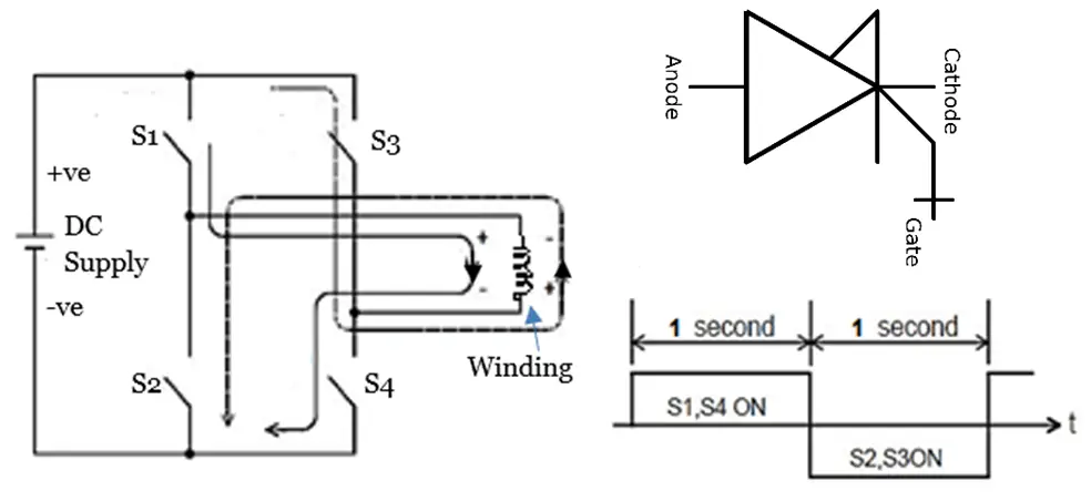
The frequency changes by changing the period to turn ON and OFF the IGBT switches S1 to S4.
For example, if the switches S1 and S4 are turned ON for 1 second and S2 and S3 for 1second and this operation is repeated, the AC with one alternation per second, i.e., the AC with a frequency of 2 Hz is created.
Speed control propulsion motor by changing frequency also will need to control voltage in proportion with frequency to keep speed and torque characteristic constant at all speed.
Pulse Width Modulation (PWM) for Voltage Control
The goal of the PWM control is to create a sine wave current waveform output to produce torque in the motor.
PWM is a way to control analog devices with a digital (On/Off) output which is used for controlling the amplitude of fixed DC voltage signals by cycling the on-and-off phases of a DC voltage signal quickly and varying the width of the “on” phase or duty cycle as seen in figure 11.
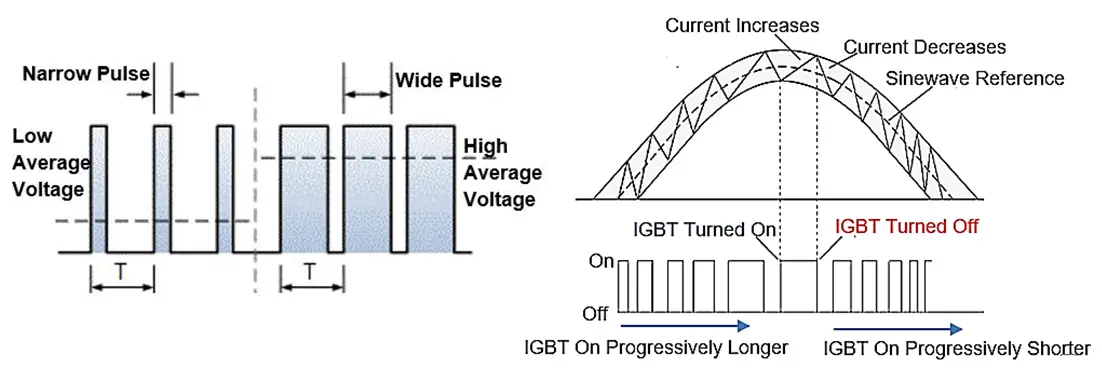
Figure 11 Voltage Variation by Pulse Width Modulation & Sinewave Current Waveform in Motor Coil
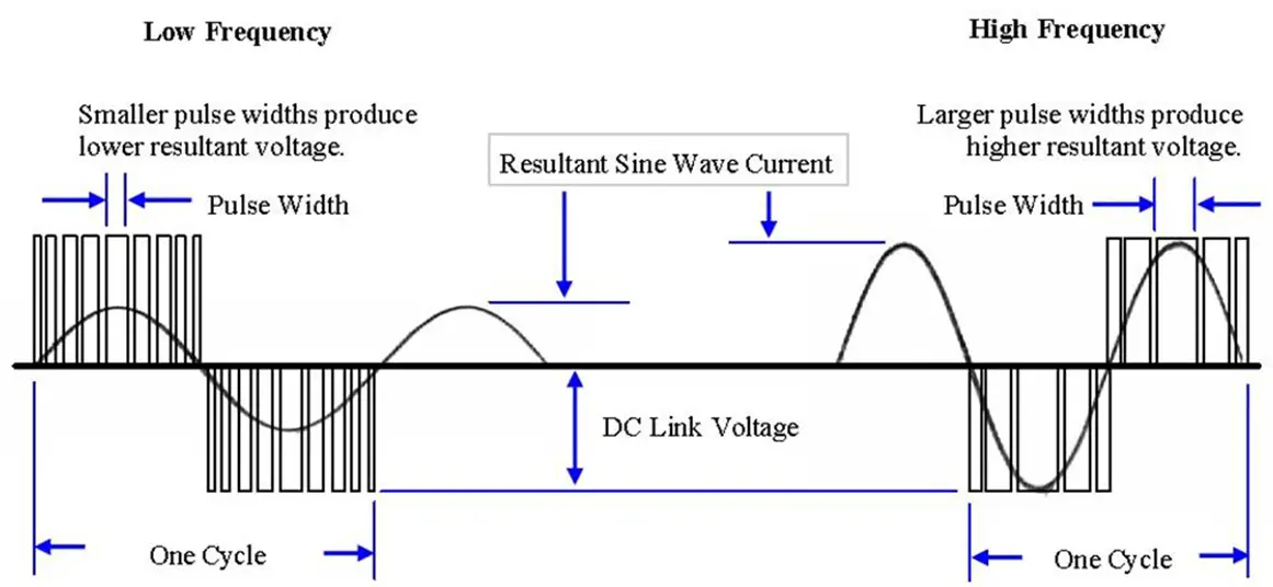
Figure 12 PWM Control to Generate Equivalent Sine Wave at High / Low Speed
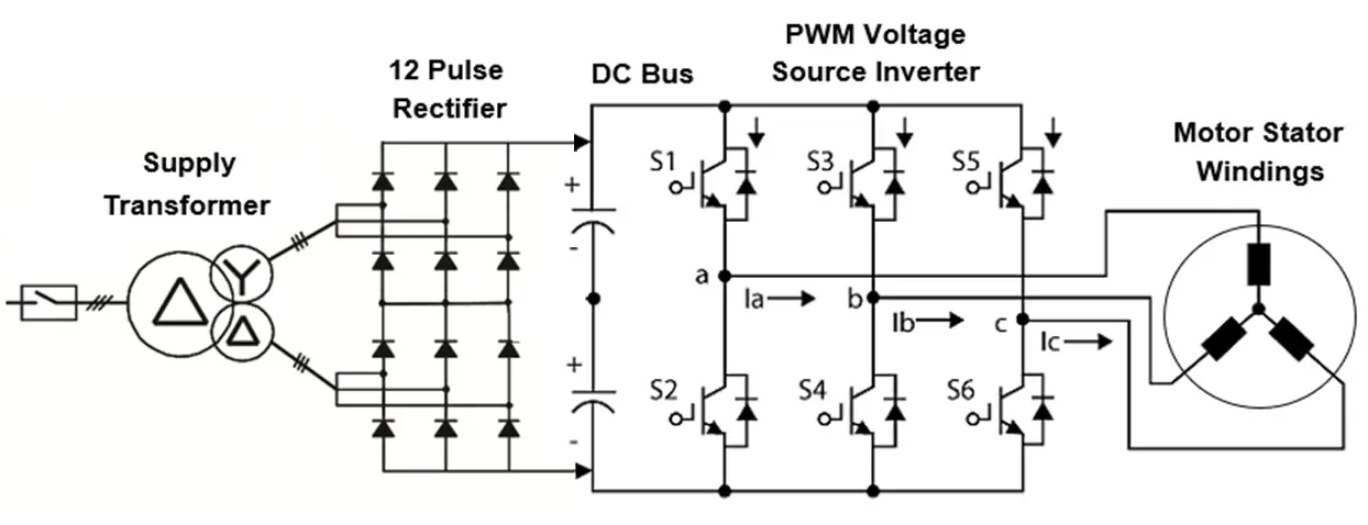
Figure 13 Motor Speed Control by IGBT switching PWM Voltage Source Inverter
The PWM (Pulse Width Modulated) drive, often also referred to as VSI (Voltage Source Inverter) is characterized by its DC voltage link which is fed from the power system by a diode rectifier. A capacitor bank is used to smooth the DC link voltage and to minimize the effect of harmonic distortion from the PWM inverter output on the supply to the motor.
Power factor around 0.955 is maintained at a constant level at all motor speeds since a diode bridge is used to produce DC voltage, the PWM drive draws almost unity power factor current from the supply source.
To produce a three-phase 120-degree phase shift between the phases in the VSI, the IGBT/IGCT/GTO switches are turned on and off at regular intervals to deliver rectangular pulses of voltage to each phase.
Figure 15 shows the line-to-line voltages of the inverter, VAB, VBC, and VCA. The line voltages are formed by connecting the line terminals of the motor to either the high or the low side of the DC bus voltage.
Three of the inverter switches as shown in figure 13 will always be closed and, at any point in time, one of the applied line voltages is zero because the three-phase motor terminals must be connected to the two DC terminals.
Every 60° one switch turns on while another turns off, resulting in the line voltages shown in Figure.
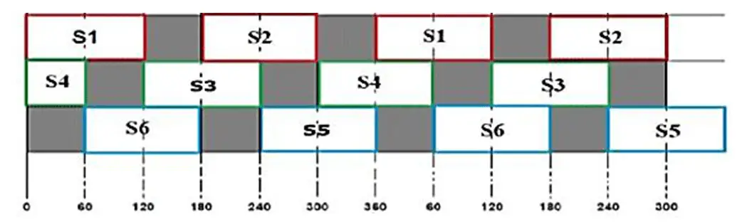
Figure 14 Switching Action of IGBT Switch every 30-degree time interval
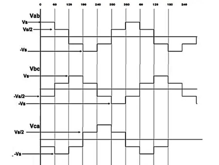
Figure 15 Voltage source inverter 3 Phase Line Voltage Waveforms