Inst ToolsInst ToolsInst Tools
  • Courses
  • Automation
    • PLC
    • Control System
    • Safety System
    • Communication
    • Fire & Gas System
  • Instrumentation
    • Design
    • Pressure
    • Temperature
    • Flow
    • Level
    • Vibration
    • Analyzer
    • Control Valve
    • Switch
    • Calibration
    • Erection & Commissioning
  • Interview
    • Instrumentation
    • Electrical
    • Electronics
    • Practical
  • Q&A
    • Instrumentation
    • Control System
    • Electrical
    • Electronics
    • Analog Electronics
    • Digital Electronics
    • Power Electronics
    • Microprocessor
  • Request
Search
  • Books
  • Software
  • Projects
  • Process
  • Tools
  • Basics
  • Formula
  • Power Plant
  • Root Cause Analysis
  • Electrical Basics
  • Animation
  • Standards
  • 4-20 mA Course
  • Siemens PLC Course
Reading: What are User Defined Function Blocks in PLC?
Share
Font ResizerAa
Inst ToolsInst Tools
Font ResizerAa
  • Courses
  • Design
  • PLC
  • Interview
  • Control System
Search
  • Courses
  • Automation
    • PLC
    • Control System
    • Safety System
    • Communication
    • Fire & Gas System
  • Instrumentation
    • Design
    • Pressure
    • Temperature
    • Flow
    • Level
    • Vibration
    • Analyzer
    • Control Valve
    • Switch
    • Calibration
    • Erection & Commissioning
  • Interview
    • Instrumentation
    • Electrical
    • Electronics
    • Practical
  • Q&A
    • Instrumentation
    • Control System
    • Electrical
    • Electronics
    • Analog Electronics
    • Digital Electronics
    • Power Electronics
    • Microprocessor
  • Request
Follow US
All rights reserved. Reproduction in whole or in part without written permission is prohibited.
Inst Tools > Blog > PLC Tutorials > What are User Defined Function Blocks in PLC?

What are User Defined Function Blocks in PLC?

Function blocks are objects which are user defined in a PLC program to simplify the process of programming.

Last updated: October 17, 2023 1:19 pm
Viral Nagda
PLC Tutorials
No Comments
Share
5 Min Read
SHARE

In this post, we will understand the use of user defined function blocks in a PLC (programmable logic controller).

Contents
Function BlocksSystem Function BlocksUser-defined Function BlocksPLC Function Block Programming Example

Function blocks are objects which are defined in a PLC program to simplify the process of programming. Basically, it is a means of reducing the programming length and complexity written by the programmer.

Consider a simple example of a timer. A timer is a logic which sets it’s output after a certain time.

Now, if a PLC programmer was required to write timer logic by himself, it would be a long and cumbersome process for him.

And, if there were many such timers required to be used in the logic, then you could imagine the length of the program code.

It would become difficult for him to troubleshoot if any issue occurs; and even difficult if some other programmer tries to study it.

This is made easier by a function block. A function block comprises of a logic written inside in it; with inputs and outputs linked to it.

So, you can use multiple instances of this function block by simply linking its inputs and outputs with different variables.

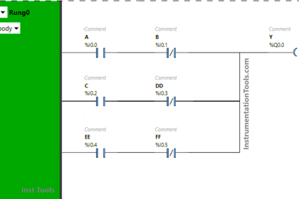
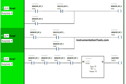
Refer to the below image. It shows two instances or uses of the timer in the program.

The first one is named alarm_t1 and the second one is named alarm_t2.

Timer in PLC Function Block

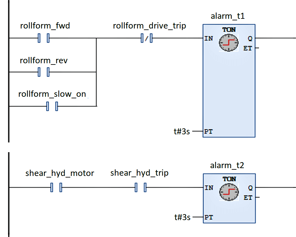
The first-timer is turned on by a different condition and the second timer is turned on by a different condition.

This shows that you can use multiple timers in the program with different trigger conditions and different set intervals.

You just have to name the timers properly; such that anyone should not clash with others.

So, consider this same thing without a function block. If it was not used, then you would have to write the logic of the timer manually; which would indirectly increase the complexities.

Function Blocks

Function blocks make the job much easier, as you do not have to write the logic every time if it is the same.

You just have to link the inputs and outputs as discussed before.

They are categorized into two types.

  1. system and
  2. user-defined.

System Function Blocks

System blocks are that function blocks that are developed by the manufacturer and preloaded in the software.

A simple example can be a timer, which we discussed before.

User-defined Function Blocks

Now, let us look ahead to our main topic. Suppose if you are writing logic to start five motors after a set interval of time. All of them are required to turn off after a set interval of time.

Now, you can use a timer here. But what about the remaining logic? If you see, it is the same; with only the number of motors varying.

Now it is five motors; tomorrow a need can be raised for six. You cannot afford to write the whole logic manually every time, as it will waste time and also resources in the PLC software.

So, PLCs have a provision for user-defined function blocks. It gives programmer the facility to create a function block by himself, and assign the inputs and outputs accordingly.

This is extremely useful in conditions where the logic repeats several times and only the inputs and outputs change.

PLC Function Block Programming Example

Refer to the below image.

Hour meter PLC function block

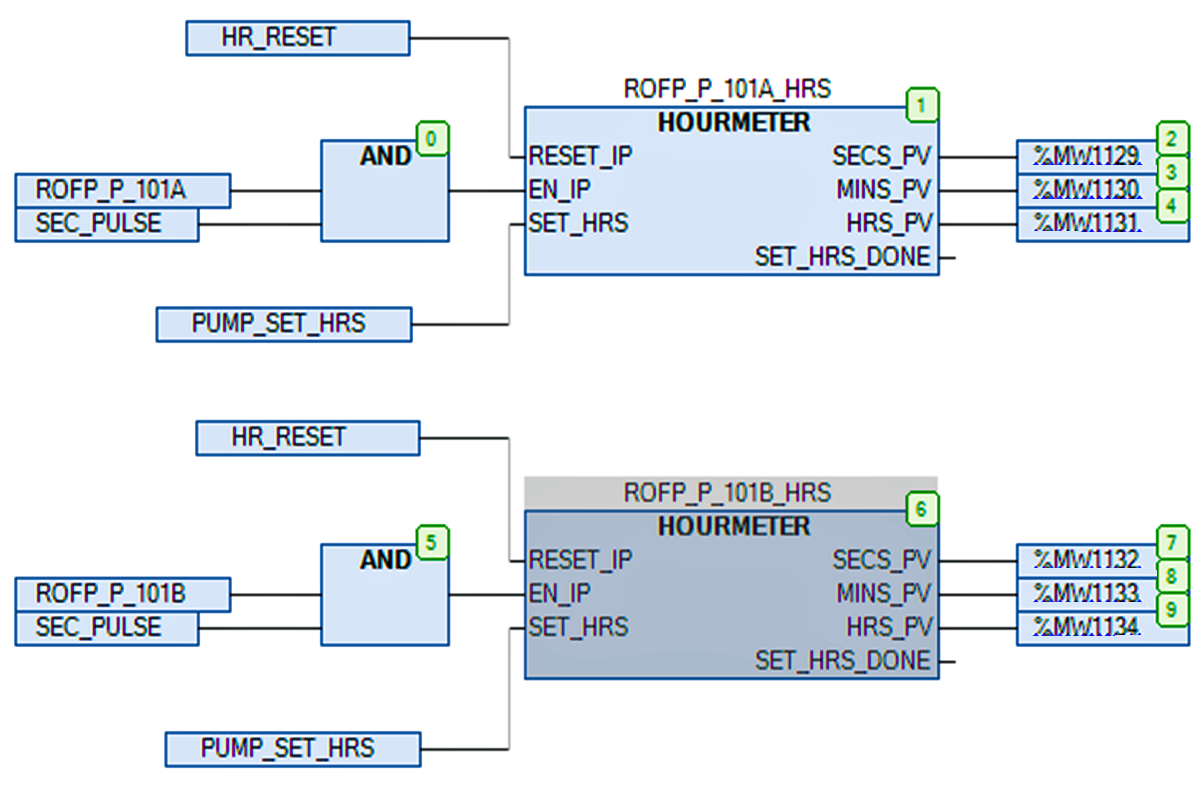
Hourmeter is a function block defined by a user which has a logic written inside by him, for counting the running hours of a pump. ROFP_P_101A_HRS is the first block and ROFP_P_101B_HRS is the second function block.

The function block has its user-defined inputs and outputs; where you just have to link the conditions according to your requirements. This makes the work very easy and time-saving; as you will not have to write the logic of running hours individually for every pump.

One more advantage is that you can use any data type inside the function block. As you can use its multiple instances, it reduces the load of the programmer and saves time indirectly.

If you liked this article, then please subscribe to our YouTube Channel for Instrumentation, Electrical, PLC, and SCADA video tutorials.

You can also follow us on Facebook and Twitter to receive daily updates.

Read Next:

  • SCADA System with OPC UA
  • PLC Digital Output Types
  • Actuator Sensor Interface
  • PLC Communication Protocols
  • PLC to PLC Communication
Don't Miss Our Updates
Be the first to get exclusive content straight to your email.
We promise not to spam you. You can unsubscribe at any time.
Invalid email address
You've successfully subscribed !

Continue Reading

Allen Bradley PLC Interview Questions and Answers
PLC Program for Automatic Lamp Control in Storage Facility
How-to do Security of SCADA Systems?
OB1 – Main Cyclic Organization Block in TIA Portal
PLC Problems Troubleshooting
Upload Option Disabled in Siemens PLC
Share This Article
Facebook Whatsapp Whatsapp LinkedIn Copy Link
Share
Leave a Comment

Leave a Reply Cancel reply

Your email address will not be published. Required fields are marked *

Stay Connected

128.3kFollowersLike
69.1kFollowersFollow
210kSubscribersSubscribe
38kFollowersFollow

Categories

Explore More

Schneider Electric: Car Parking System with Calculations in PLC
What is Loop Checking?
How to Start Writing SCL Language in Siemens Tia Portal?
Top 100 PLC Projects List
Automatic Coffee Vending Machine – PLC Logic Programming
Design Document for Project Systems Architecture
How to Connect a Solenoid Valve with PLC?
Laws of Boolean Algebra using Ladder Logic

Keep Learning

SCADA and PLC Configuration

Examples of SCADA and PLC Configuration Systems

PLC Program to control level of parallel tanks

Parallel Tanks Level Control using PLC Ladder Diagram Tutorial

What is a Tag in SCADA

What is a Tag? Types of Tags in SCADA

PLC Program for fan control unit system

PLC Programming for Fan Control Unit System for Industry

Pneumatic valve operation in sequence mode

Sequential PLC Programming for the Pneumatic Valves

Sorting PLC Program Simulation

Sorting & Distribution Line PLC Programming – Advanced Logic

scada hmi

Functions of SCADA

Jog button in Motor Start Stop Logic using PLC

What is Motor Jogging ?

Learn More

Types of Limit Switches

Types of Limit Switches – Principle, Advantages, Disadvantages

Gas Filter Correlation (GFC) spectrometer

Gas Filter Correlation (GFC) Spectroscopy

Sugar Plant - Automatic Control of Massecuite Feed

Sugar Plant – Automatic Control of Massecuite Feed

Mass Flow Calculations of flow measurement

Mass Flow Calculations

Power MOSFET Safe Operating Area

Power MOSFET Safe Operating Area

Difference between SR Flipflop and RS Flipflop

Difference between SR Flipflop and RS Flipflop ?

Power Electronics Projects

Top 100 Power Electronics Projects for Engineering Students

Power Supply Circuit Working Animation

Power Supply Circuit Working Animation

Menu

  • About
  • Privacy Policy
  • Copyright

Quick Links

  • Learn PLC
  • Helping Hand
  • Part Time Job

YouTube Subscribe

Follow US
All rights reserved. Reproduction in whole or in part without written permission is prohibited.
Welcome Back!

Sign in to your account

Username or Email Address
Password

Lost your password?