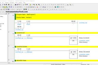
Write a PLC program to count the number of cars in the garage knowing that the entrance and the exit of the garage are the same one door.
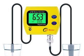
There are 2 photocells one in the outer side of the garage and the other in the inner side.
Note the best practice to learn the PLC programming is to start writing the PLC program, take your time before you review the answer.
Inputs & outputs
I0.0: outer photocell
I0.1: inner photocell
I0.2: reset
C1: Counter.
T1: Timer 01
T2: Timer 02
MW10: counter-current value.
M0.1: count up.
M0.5: count down.
PLC Logic
- In this example, we rely on the concept of positive edge and negative edge.
- When the car enters the garage the outside photocell is energized first after that the inside photocell would be energized in order.
- So to detect that the car is entering the garage the outside sensor negative edge should be detected after that the positive edge of the inside photocell. And vice versa for the car comes out from the garage.
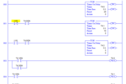
Network 01
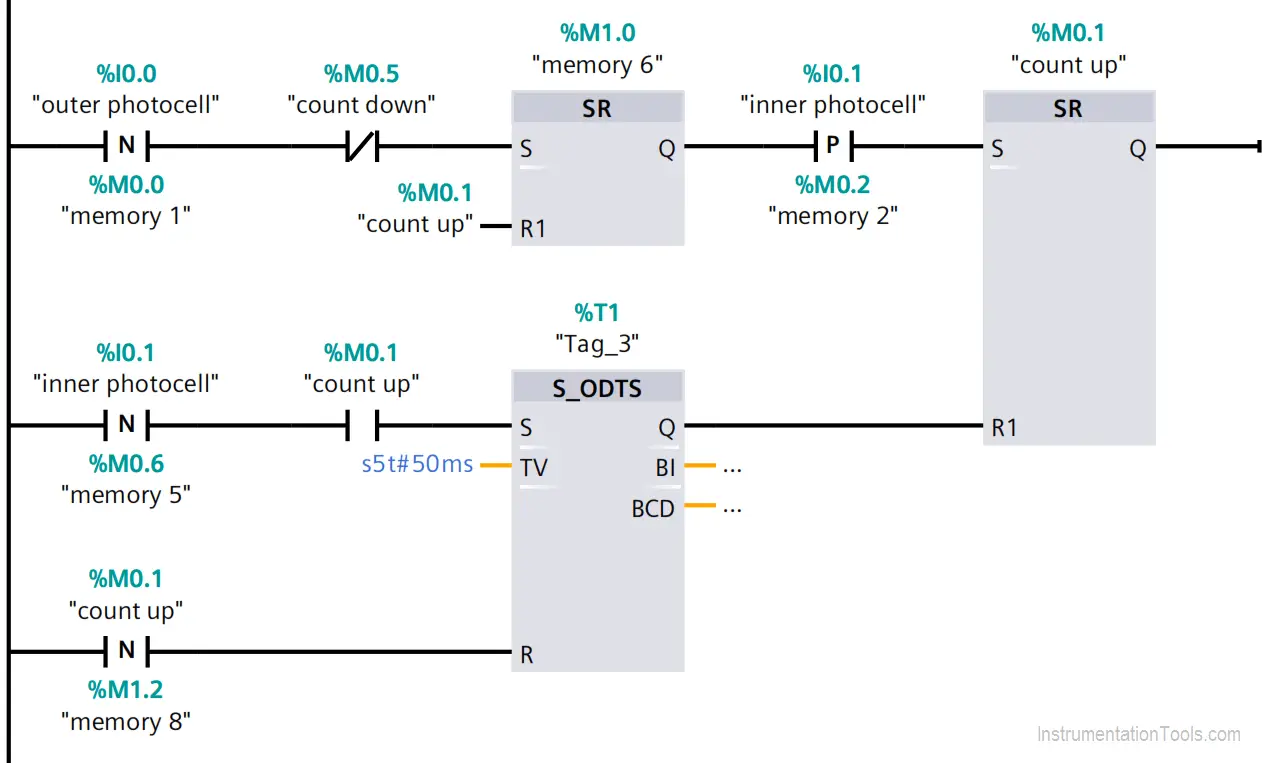
In case of the count-down, memory is off and the negative edge of the outer photocell detected then energizes the memory bit in the flip flop and resets it in the case of counting up.
After that, the next step is to detect the positive edge of the inner photocell to set the memory bit of counting up.
To reset the count up SR flip flop the negative edge of the inner photocell should be detected in case of counting up after a delay of 50 ms, that delay is to ensure the interlocking between the counting up and counting down.
As it’s an extended on delay timer a reset bit should be added, so the count up memory should reset the timer.
Network 02
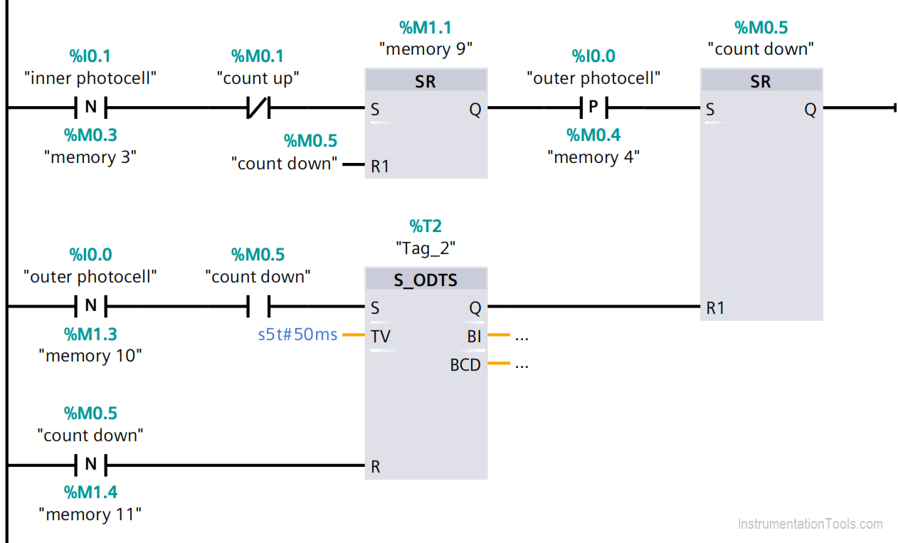
In case of the count up memory is off and the negative edge of the inner photocell detected then energizes the memory bit in the flip flop and resets it in the case of counting down.
After that, the next step is to detect the positive edge of the outer photocell to set the memory bit of counting down.
To reset the countdown SR flip flop the negative edge of the outer photocell should be detected in case of counting down after a delay of 50 ms, that delay is to ensure the interlocking between the counting up and counting down.
As it’s an extended on delay timer a reset bit should be added, so the countdown memory should reset the timer.
Network 03
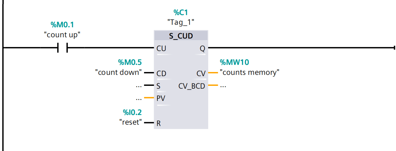
The count up memory increment the counter by one, and the count down memory decrement the counter by one.
The reset button resets the counter counts value to 0.
The counter counts value is registered in the MW10.
Author: Karim Ali Anwar
If you liked this article, then please subscribe to our YouTube Channel for PLC and SCADA video tutorials.
You can also follow us on Facebook and Twitter to receive daily updates.
Read Next: