Inst ToolsInst ToolsInst Tools
  • Courses
  • Automation
    • PLC
    • Control System
    • Safety System
    • Communication
    • Fire & Gas System
  • Instrumentation
    • Design
    • Pressure
    • Temperature
    • Flow
    • Level
    • Vibration
    • Analyzer
    • Control Valve
    • Switch
    • Calibration
    • Erection & Commissioning
  • Interview
    • Instrumentation
    • Electrical
    • Electronics
    • Practical
  • Q&A
    • Instrumentation
    • Control System
    • Electrical
    • Electronics
    • Analog Electronics
    • Digital Electronics
    • Power Electronics
    • Microprocessor
  • Request
Search
  • Books
  • Software
  • Projects
  • Process
  • Tools
  • Basics
  • Formula
  • Power Plant
  • Root Cause Analysis
  • Electrical Basics
  • Animation
  • Standards
  • 4-20 mA Course
  • Siemens PLC Course
Reading: Relationship between Temperature Scales
Share
Font ResizerAa
Inst ToolsInst Tools
Font ResizerAa
  • Courses
  • Design
  • PLC
  • Interview
  • Control System
Search
  • Courses
  • Automation
    • PLC
    • Control System
    • Safety System
    • Communication
    • Fire & Gas System
  • Instrumentation
    • Design
    • Pressure
    • Temperature
    • Flow
    • Level
    • Vibration
    • Analyzer
    • Control Valve
    • Switch
    • Calibration
    • Erection & Commissioning
  • Interview
    • Instrumentation
    • Electrical
    • Electronics
    • Practical
  • Q&A
    • Instrumentation
    • Control System
    • Electrical
    • Electronics
    • Analog Electronics
    • Digital Electronics
    • Power Electronics
    • Microprocessor
  • Request
Follow US
All rights reserved. Reproduction in whole or in part without written permission is prohibited.
Inst Tools > Blog > Formulas > Relationship between Temperature Scales

Relationship between Temperature Scales

Last updated: July 25, 2019 3:24 pm
Editorial Staff
Formulas Temperature Measurement
No Comments
Share
2 Min Read
SHARE

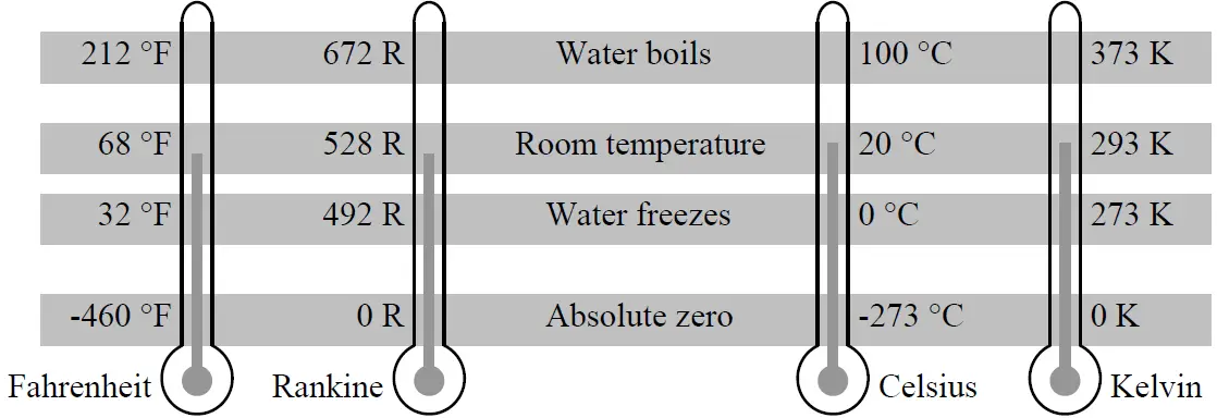
Relationship between Temperature Scales

Relationship between Temperature Scales

Contents
Relationship between Temperature ScalesRelationship between Fahrenheit and CelsiusQuickly Convert Between Temperatures:

Relationship between Fahrenheit and Celsius

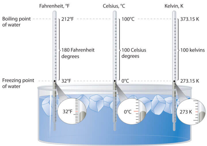
To determine the relationship between Fahrenheit and Celsius, we could draw a graph of F (temperature in °F) versus C (temperature in °C), for C in the range 0 ≤ C ≤ 100.
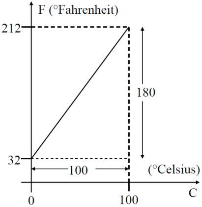
Relationship between Fahrenheit and Celsius

Using the general equation for a straight line:

y = m x + c

using the general straight line equation and above graph, the following equation obtained
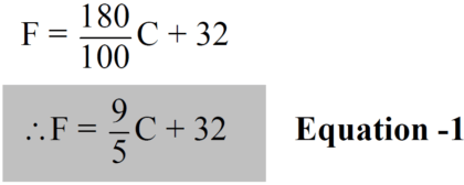
Fahrenheit to Celsius Formula

We can now also express Celsius in terms of Fahrenheit. From Equation -1:
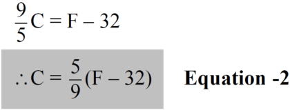
Celsius to Fahrenheit Formula

Now we solved the basic formulas for conversion of Celsius to Fahrenheit or vice versa. Using the same above procedure we can also calculate the relationship between different temperature scales.

Quickly Convert Between Temperatures:

  • Celsius to Fahrenheit: Multiply the temperature by 2 and then add 30
  • Fahrenheit to Celsius: subtract 30 from the temp. and then divide by 2
  • Kelvin to Fahrenheit: Subtract 273.15, multiply by 1.8, then add 32
  • Fahrenheit to Kelvin: Subtract 32, multiply by 5, divide by 9, then add 273.15
  • Kelvin to Celsius: Add 273
  • Celsius to Kelvin: Subtract 273

Relationship between Different Temperatures

Example -1

Convert the absolute zero of temperature (–273.15 °C), to degrees Fahrenheit.

F = (9/5)C + 32 = (9/5)×(-273.15) + 32 = -459.67 °F ≈ -460 °F

Example -2

Convert 86 °F into degrees Celsius, Rankine and Kelvin.

C = (5/9)(F – 32) = (5/9)×(86 – 32) = 30 °C

R = F + 460 = 86 + 460 = 546 R

K = C + 273 = 30 + 273 = 303 K

Example -3

Determine the temperature in degrees Fahrenheit that would translate into the same value in degrees Celsius.

In Equation -2 (or Equation -1), set C = F:

F = (5/9)(F – 32) ⇒ 9F = 5F – 160 ⇒ 4F = -160 ⇒ F = -40 °F

Example -4

Convert 0 °F to degrees Celsius.

C = (5/9)(F – 32) = (5/9)(0 – 32) = -17.78 °C

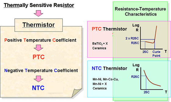
Also Read: Thermistor Working Principle
Don't Miss Our Updates
Be the first to get exclusive content straight to your email.
We promise not to spam you. You can unsubscribe at any time.
Invalid email address
You've successfully subscribed !

Continue Reading

DP Level Transmitter Elevation and Suppression Corrections
PLC Analog Input Conversion Formula
What Temperature are Celsius and Fahrenheit Value Same ?
Bi-metal Temperature Sensors
Temperature Coefficient of Resistance (α)
Why Thermocouple Reference Junction Compensation Required ?
Share This Article
Facebook Whatsapp Whatsapp LinkedIn Copy Link
Share
Leave a Comment

Leave a Reply Cancel reply

Your email address will not be published. Required fields are marked *

Stay Connected

128.3kFollowersLike
69.1kFollowersFollow
210kSubscribersSubscribe
38kFollowersFollow

Categories

Explore More

Thermocouples Connector and Tip styles
Temperature Transmitter Preventive Maintenance
How 3 Wire RTD Lead Wire Resistance Eliminated?
What to Choose RTD or Thermocouple ?
How to calculate the tolerance of a RTD sensor
RTD Calibration Procedure
Types of Thermocouple Measuring Junction
Calculate Process Variable from Transmitter Current

Keep Learning

RTD Calculator Software

RTD Calculator Software

Basic Temperature Sensors MCQ

Basic Temperature Sensors MCQ Questions Answers

Different RTD Types

Difference between PT100, PT1000, Nickel RTD and Balco RTD

Temperature Sensors Interview Questions

Temperature Sensors Interview Questions

input-output-relationships-of-transmitters

Input-Output Relationships of Transmitters

Thermocouple Temperature Measurements Errors

Thermocouple Temperature Measurement Errors

PTC NTC Thermistors Comparation

Thermistor Working Principle
Pyrometer

Pyrometers Handbook

Learn More

Liquid Level Measurement using Pressure Transmitter

Liquid Level Measurement using Pressure Transmitter Questions

What is calibration?

Save to Memory Card

How to Save a PLC Project to a Micro Memory Card?

What is a Time Delay Relay

What is a Time Delay Relay? Principle, Advantages, Disadvantages

Encoder Principle

Encoder Working Principle

On Off Valve Root Cause Analysis

Root Cause Analysis for FRP Line Damaged due to On-Off Valve

Instrument Percent of Span Error

Instrument Percent of Span Error

Capacitively Coupled Multistage Transistor Amplifier

Capacitively Coupled Multistage Transistor Amplifier

Menu

  • About
  • Privacy Policy
  • Copyright

Quick Links

  • Learn PLC
  • Helping Hand
  • Part Time Job

YouTube Subscribe

Follow US
All rights reserved. Reproduction in whole or in part without written permission is prohibited.
Welcome Back!

Sign in to your account

Username or Email Address
Password

Lost your password?