4-20 mA instrumentation and controls usually support a signal range slightly below 4 mA and above 20 mA.
For transmitters, current values below 4 mA and above 20 mA are used to signal a fault such as a thermocouple burnout, Signal cable broken, Cable Low/High Resistance, Transmitter Failure or other sensor failure.
The transmitter can be configured for failure indication low or high.
Unfortunately manufacturers use different signal levels to indicate failure which prevents tight analog signal integration and interpretation in single loop controllers, control systems, and safety systems.
Transmitters 4-20mA Current Failure Alarm Limits
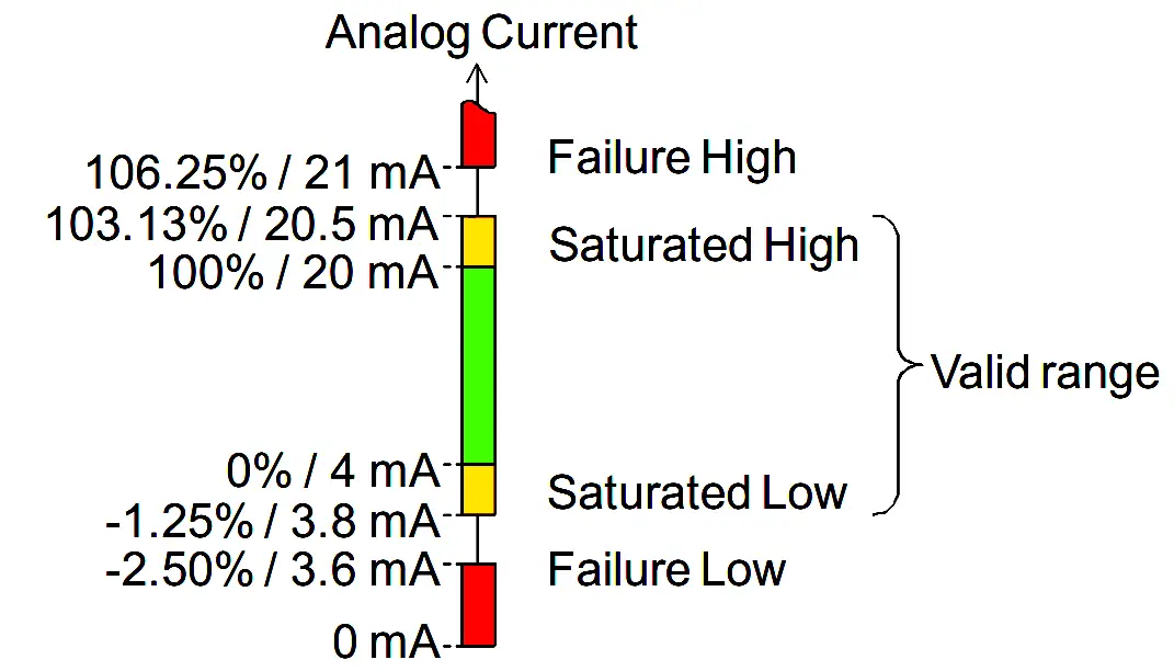
Image Source : eddl.org
Some transmitters may use 3.75 mA while others may use 3.6 mA or less. Some transmitter may use 21.75 mA or more while other use 23 mA.
This inconsistency of signal levels for failure indication makes it difficult to take full advantage of the failure information in control strategies.
The NAMUR NE43 “Standardization of the Signal Level for the Failure Information of Digital Transmitters” recommendation was created to standardize failure indication from transmitters and interpretation in control systems to enable better analog integration.
NE43 defines 3.8 to 20.5 mA as a valid (‘Good’) measurement value where 3.8 to 4 and 20 to 20.5 mA indicates saturation.
A signal of <3.6 mA or >21 mA indicates a transmitter failure (‘Bad’).

Image Source : eddl.org
By using transmitters and systems that both conform to the NE43 recommendation, it is possible to flag faults to the operators and control strategies.
However, note that all device errors, severe and trivial, are flagged the same way so the operator cannot tell the difference and that if any error occurs it is flagged and the measurement value is not provided.
FOUNDATION fieldbus and PROFIBUS-PA transmitters use digital communication with separate status indication for each measurement including measurement validity flagged in realtime as ‘Good’, ‘Bad’, or ‘Uncertain’.
This allows operators and control strategies to severe problems from trivial issues. This allows the control strategy to put the loop in manual in case of failure, with the option to trip. For non-severe issues the value is still displayed with ‘Uncertain’ status.
Smart Valve Positioners
Smart valve positioners are not in the scope of NAMUR NE43.
However, signals <4 mA and >20 mA also have specific meanings. Control systems and single loop controllers with 4-20 mA output use a similar scheme to achieve tight shut-off for control valves. That is, they may set current <<4 mA or >>20 mA.
Some control systems set the output current to 0 mA to achieve tight shutoff. This is impractical in the case of smart valve positioners since they need 3.6 mA to operate and will be completely switched off at 0 mA.
Therefore make sure to configure the control system or single loop controller to provide at least 3.6 or 3.8 mA for tight shutoff to ensure that the smart valve positioner can continue to operate and respond to HART communication.
Source : Eddl.org
If you liked this article, then please subscribe to our YouTube Channel for PLC and SCADA video tutorials.
You can also follow us on Facebook and Twitter to receive daily updates.
Read Next:


Please share topics on floating voltages and grounded voltage… Thanx.
Excellent.
very good ..article…!!!…Thanks
Fine tips
Inst video is very good