Inst ToolsInst ToolsInst Tools
  • Courses
  • Automation
    • PLC
    • Control System
    • Safety System
    • Communication
    • Fire & Gas System
  • Instrumentation
    • Design
    • Pressure
    • Temperature
    • Flow
    • Level
    • Vibration
    • Analyzer
    • Control Valve
    • Switch
    • Calibration
    • Erection & Commissioning
  • Interview
    • Instrumentation
    • Electrical
    • Electronics
    • Practical
  • Q&A
    • Instrumentation
    • Control System
    • Electrical
    • Electronics
    • Analog Electronics
    • Digital Electronics
    • Power Electronics
    • Microprocessor
Search
  • Books
  • Software
  • Projects
  • Process
  • Tools
  • Basics
  • Formula
  • Power Plant
  • Root Cause Analysis
  • Electrical Basics
  • Animation
  • Standards
  • 4-20 mA Course
  • Siemens PLC Course
Reading: Tuning a Temperature Process Control Loop
Share
Notification Show More
Font ResizerAa
Inst ToolsInst Tools
Font ResizerAa
  • Courses
  • Design
  • PLC
  • Interview
  • Control System
Search
  • Courses
  • Automation
    • PLC
    • Control System
    • Safety System
    • Communication
    • Fire & Gas System
  • Instrumentation
    • Design
    • Pressure
    • Temperature
    • Flow
    • Level
    • Vibration
    • Analyzer
    • Control Valve
    • Switch
    • Calibration
    • Erection & Commissioning
  • Interview
    • Instrumentation
    • Electrical
    • Electronics
    • Practical
  • Q&A
    • Instrumentation
    • Control System
    • Electrical
    • Electronics
    • Analog Electronics
    • Digital Electronics
    • Power Electronics
    • Microprocessor
Follow US
All rights reserved. Reproduction in whole or in part without written permission is prohibited.
Inst Tools > Blog > Control Systems > Tuning a Temperature Process Control Loop

Tuning a Temperature Process Control Loop

Last updated: February 28, 2019 12:00 pm
Editorial Staff
Control Systems
No Comments
Share
4 Min Read
SHARE

Tuning a Temperature Process Control Loop

Ziegler-Nichols open-loop tuning procedure

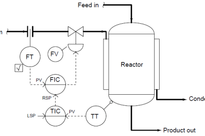
This next simulated process is a temperature control process. Performing an open-loop test (two 10% increasing output step-changes, both made in manual mode) on this process resulted in the following behavior:

Tuning a Temperature Process Control Loop

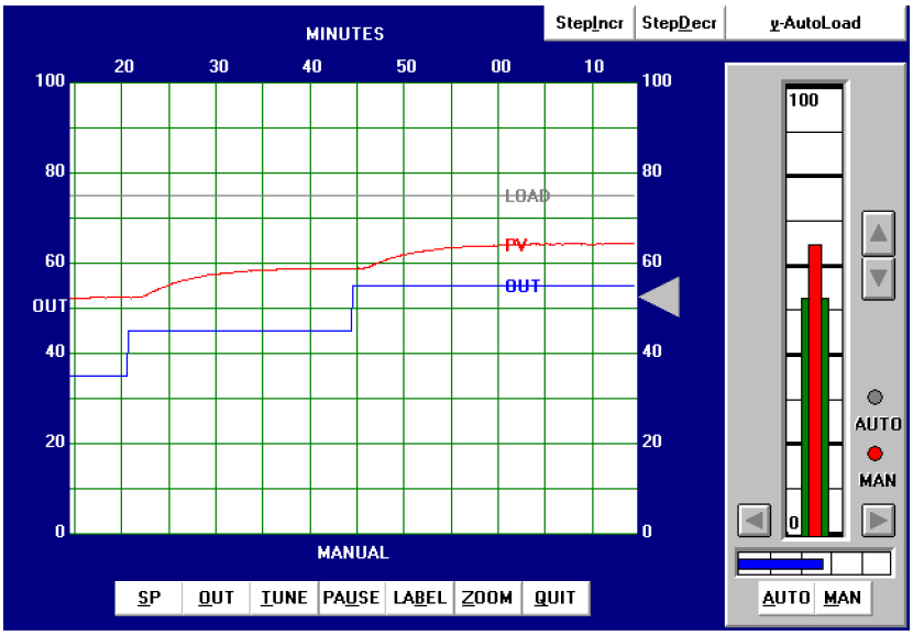
From the trend, the process appears to be self-regulating with a slow time constant (lag) and a substantial dead time. The reaction rate (R) on the first step-change is 30% over 30 minutes, or 1 percent per minute. Dead time (L) looks to be approximately 1.25 minutes. Following the Ziegler- Nichols recommendations for PID tuning based on these process characteristics (also including the 10% step-change magnitude Δm):

Tuning a Temperature Process Control Formula

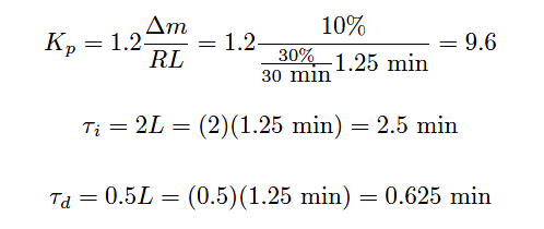
Applying the PID values of 9.6 (gain), 2.5 minutes per repeat (integral), and 0.625 minutes (derivative) gave the following result in automatic mode:

Tuning a Temperature Process Control

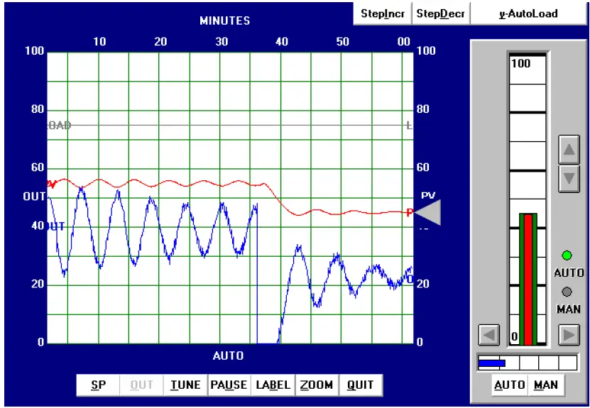
As you can see, the results are quite poor. The PV is still oscillating with a peak-to-peak amplitude of almost 20% from the last process upset at the time of the 10% downward SP change. Additionally, the output trend is rather noisy, indicating excessive amplification of process noise by the controller.

Also Read : Ziegler-Nichols Open-Loop Theory

Ziegler-Nichols closed-loop tuning procedure

Next, the closed-loop, or “Ultimate” tuning method of Ziegler and Nichols was applied to this process. Eliminating both integral and derivative control actions from the controller, and experimenting with different gain (proportional) values until self-sustaining oscillations of consistent amplitude were obtained, gave a gain value of 15:

Ziegler-Nichols tuning

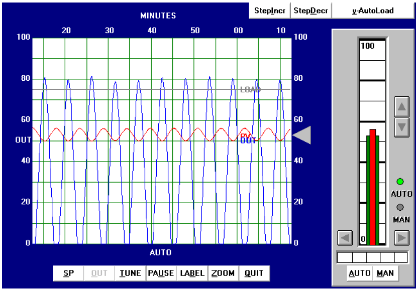
From the trend, we can see that the ultimate period (Pu) is approximately 5.2 minutes in length. Following the Ziegler-Nichols recommendations for PID tuning based on these process characteristics:

Ziegler-Nichols closed-loop

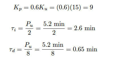
These PID tuning values are quite similar to those predicted by the open loop (“Reaction Rate”) method, and so we would expect to see very similar results:

Ziegler-Nichols closed-loop Formula

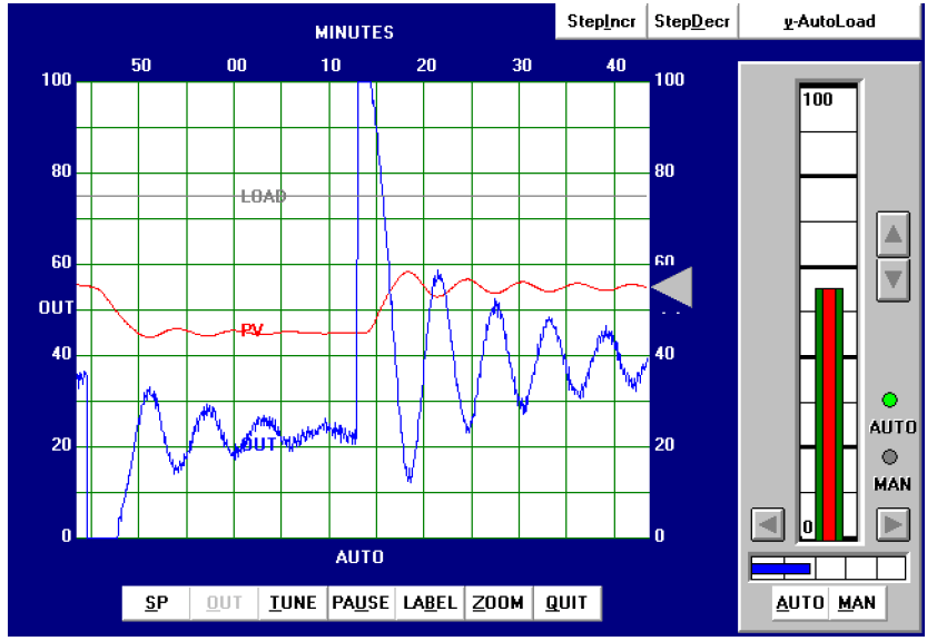
As expected, we still see excessive oscillation following a 10% setpoint change, as well as excessive “noise” in the output trend.

Also Read : Ziegler-Nichols Closed-Loop Theory

Heuristic tuning procedure

From the initial open-loop (manual output step-change) test, we could see this process was selfregulating with a slow lag and substantial dead time. The self-regulating nature of the process demands at least some integral control action to eliminate offset, but too much will cause oscillation given the long lag and dead times. The existence of over 1 minute of process dead time also prohibits the use of aggressive proportional action. Derivative action, which is generally useful in overcoming lag times, will cause problems here by amplifying process noise. In summary, then, we would expect to use mild proportional, integral, and derivative tuning values in order to achieve good control with this process. Anything too aggressive will cause problems for this process.

After some experimenting, the values I arrived at were 3 (gain), 5 minutes (integral), and 0.5 minutes (derivative). These tuning values represent a proportional action only one-third as aggressive as the Ziegler-Nichols recommendation, and an integral action about half as aggressive as the Ziegler- Nichols recommendation. The results of these tuning values in automatic mode are shown here:

Heuristic loop tuning procedure

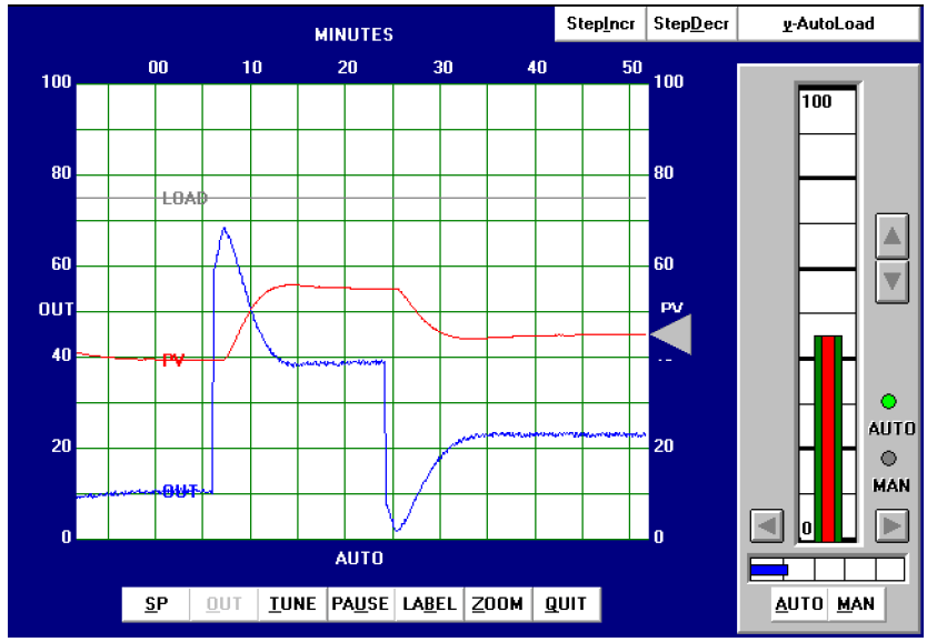
As you can see, the system’s response has almost no overshoot (with either a 10% setpoint change or a 15% setpoint change) and very little “noise” on the output trend. Response to setpoint changes is relatively crisp considering the naturally slow nature of the process: each new setpoint is achieved within about 7.5 minutes of the step-change.

Also Read : Heuristic PID Tuning Theory

Don't Miss Our Updates
Be the first to get exclusive content straight to your email.
We promise not to spam you. You can unsubscribe at any time.
Invalid email address
You've successfully subscribed !

Continue Reading

Grounding or Earthing Scheme in DCS or PLC Systems
Integrating Processes – Liquid Level Control
20 Most Common Types of Cyber Attacks
Process Interlocks and Trips
Loop-powered 4-20 mA Transmitter Circuit Voltage drop
Ziegler-Nichols Open-Loop Method
Share This Article
Facebook Whatsapp Whatsapp LinkedIn Copy Link
Share
Leave a Comment

Leave a Reply Cancel reply

Your email address will not be published. Required fields are marked *

Stay Connected

128.3kFollowersLike
69.1kFollowersFollow
208kSubscribersSubscribe
38kFollowersFollow

Categories

Explore More

Evaluating Industrial Automation Projects Return on investment (ROI)
Automation System Process Functionalities
Why Baud Rate is Important in Modbus Network?
Functional Design Specifications for DCS and SIS Projects – FDS Document
Analysis of HART communicator and Smart HART Transmitter
What is DeviceNet?
Industrial Automation System Architecture Reference Model
Industrial Automation and Control Systems (IACS)

Keep Learning

Compare DCS, PLC, RTU

Difference between DCS, PLC, and RTU ?

21 CFR in SCADA and HMI Systems

What is 21 CFR in SCADA and HMI Systems?

Cable Glands

Using of MCT instead of Cable Glands on the Cabinets

What is Process Control ?

What is Process Control?

2-wire loop-powered transmitter

Loop Controller HART Signal Noise

Integral Control Principle

Integral Controller Principle

PID Controller Functions

PID Controller Functions

DCS Commissioning Steps

DCS Commissioning Steps

Learn More

liquid level Measurement

Hydrostatic Level Measurement – Temperature related Density Change Effects

kirchhoffs-voltage-law

What is Kirchhoff’s Voltage Law

Top 80+ Valve Questions and Answers

Top 80+ Valve Questions and Answers

The Best HVAC System for Home

Which HVAC System is Best for Home?

Earth Meter Working Principle

How Earth Resistance is Measured

Differential Pressure Transmitters Static Pressure

What is Static Pressure Limit in DP Transmitter ?

Internal Parts of Globe Valve

How to Choose a Control Valve?

Electrical Machines Questions and Answers

Armature Quiz

Follow US
All rights reserved. Reproduction in whole or in part without written permission is prohibited.
Welcome Back!

Sign in to your account

Username or Email Address
Password

Lost your password?