In the broadest sense, a “selector” control strategy is where one signal is selected from multiple signals in a system to perform a measurement control function.
I will use the term “selector” to reference automatic selection among multiple measurement or setpoint signals.
Selection between multiple controller output signals will be explored in the next subsection, under the term “override” control.
Perhaps one of the simplest examples of a selector control strategy is where we must select a process variable signal from multiple transmitters.
For example, consider this chemical reactor, where the control system must throttle the flow of coolant to keep the hottest measured temperature at setpoint, since the reaction happens to be exothermic (heat-releasing):
Note : Only the coolant flow control instruments and piping are shown in this diagram, for simplicity. In a real P&ID, there would be many more pipes, valves, and other apparatus shown surrounding this process vessel.
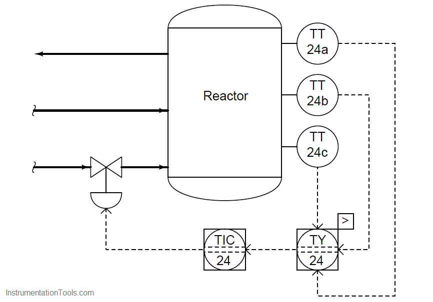
The high-select relay (TY-24) sends only the highest temperature signal from the three transmitters to the controller. The other two temperature transmitter signals are simply ignored.
Another use of selector relays (or function blocks) is for the determination of a median process measurement. This sort of strategy is often used on triple-redundant measurement systems, where three transmitters are installed to measure the exact same process variable, providing a valid measurement even in the event of transmitter failure.
The median select function may be implemented one of two ways using high- and low-select function blocks:
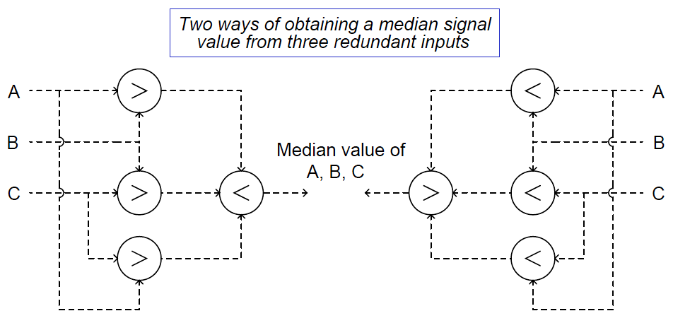
The left-hand selector strategy selects the highest value from each pair of signals (A and B, B and C, A and C), then selects the lowest value of those three primary selections.
The right-hand strategy is exactly opposite – first selecting the lowest value from each input pair, then selecting the highest of those values – but it still accomplishes the same function. Either strategy outputs the middle value of the three input signals.
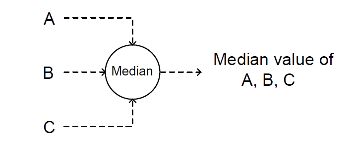
Although either of these methods of obtaining a median measurement requires four signal selector functions, it is quite common to find function blocks available in control systems ready to perform the median select function all in a single block.
The median-select function is so common to redundant sensor control systems that many control system manufacturers provide it as a standard function unto itself:
This is certainly true in the FOUNDATION Fieldbus standard, where two standardized function blocks are capable of this function, the CS (Control Selector) and the ISEL (Input Selector) blocks:
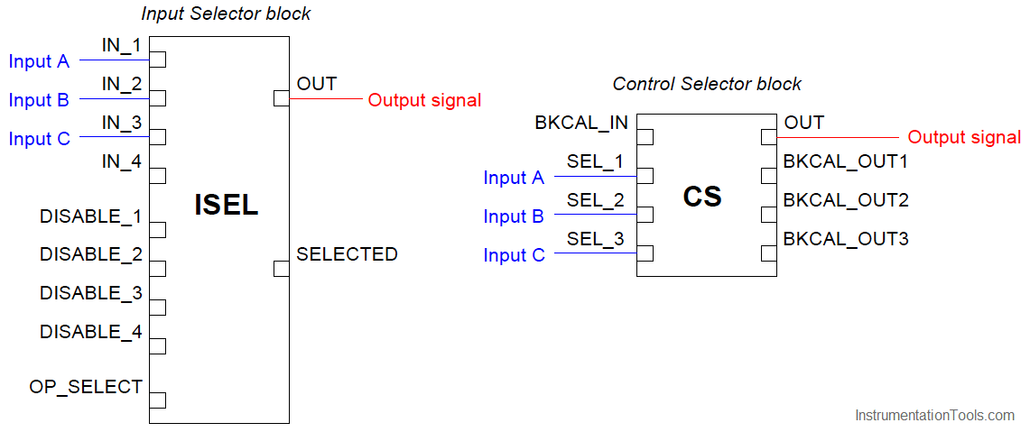
Of these two Fieldbus function blocks, the latter (ISEL) is expressly designed for selecting transmitter signals, whereas the former (CS) is best suited for selecting controller outputs with its “back calculation” facilities designed to modify the response of all de-selected controllers.
Using the terminology of this book section, the ISEL function block is best suited for selector strategies, while the CS function block is ideal for limit and override strategies (discussed in the next section).
If receiving three “good” inputs, the ISEL function block will output the middle (median) value of the three. If one of the inputs carries a “bad” status, the ISEL block outputs the averaged value of the remaining two (good) inputs.
Note how this function block also possesses individual “disable” inputs, giving external boolean (on/off) signals the ability to disable any one of the transmitter inputs to this block.
Thus, the ISEL function block may be configured to de-select a particular transmitter input based on some programmed condition other than internal diagnostics.
If receiving four “good” inputs, the ISEL function block normally outputs the average value of the two middle (median) signal values. If one of the four inputs becomes “bad” is disabled, the block behaves as a normal three-input median select.
A general design principle for redundant transmitters is that you never install exactly two transmitters to measure the same process variable. Instead, you should install three (minimum).
The problem with having two transmitters is a lack of information for “voting” if the two transmitters happen to disagree.
In a three-transmitter system, the function blocks may select the median signal value, or average the “best 2 out of 3.” If there are just two transmitters installed, and they do not substantially agree with one another, it is anyone’s guess which one should be trusted.
A classic example of selectors in industrial control systems is that of a cross-limited ratio control strategy for air/fuel mixture applications.
Before we explore the use of selector functions in such a strategy, we will begin by analyzing a simplified version of that strategy, where we control air and fuel flows to a precise ratio with no selector action at all:
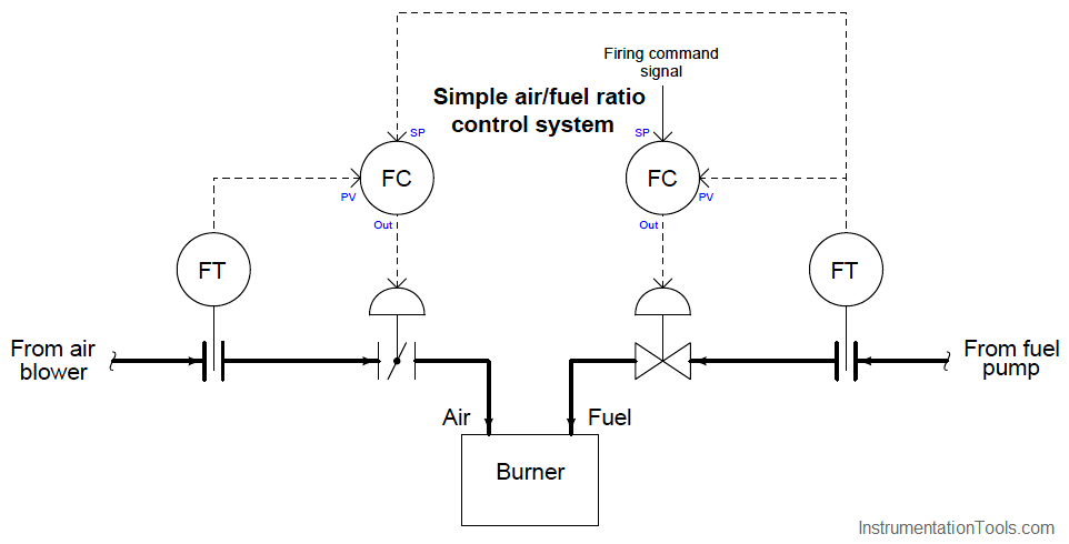
Here, the fuel flow controller receives its setpoint directly from the firing command signal, which may originate from a human operator’s manual control or from the output of a temperature controller regulating temperature of the combustion-heated process.
The air flow controller receives its setpoint from the fuel flow transmitter, with the calibrations of the air and fuel flow transmitters being appropriate to establish the proper air:fuel flow ratio when the transmitters register equally.
From the perspective of the air flow controller, fuel flow is the wild flow while air flow is the captive flow.
There is a problem with this control system that may not be evident upon first inspection: the air:fuel ratio will tend to vary as the firing command signal increases or decreases in value over time.
This is true even if the controllers are well-tuned and the air:fuel ratio remains well-controlled under steady-state conditions. The reason for this is linked to the roles of “wild” and “captive” flows, fuel and air flow respectively.
Since the air flow controller receives its setpoint from the fuel flow transmitter, changes in air flow will always lag behind changes in fuel flow.
This sort of problem can be difficult to understand because it involves changes in multiple variables over time.
A useful problem-solving technique to apply here is a “thought experiment,” coupled with a time-based graph to display the results.
Our thought experiment consists of imagining what would happen if the firing command signal were to suddenly jump in value, then sketching the results on a graph.
If the firing command signal suddenly increases, the fuel flow controller responds by opening up the fuel valve, which after a slight delay results in increased fuel flow to the burner.
This increased fuel flow signal gets sent to the setpoint input of the air flow controller, which in turn opens up the air valve to increase air flow proportionately.
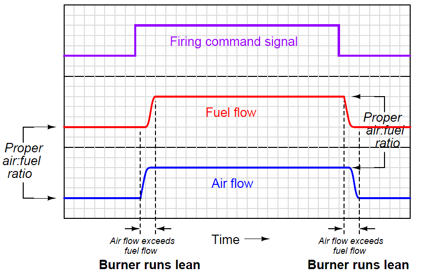
If the firing command signal suddenly decreased, the same changes in flow would occur in reverse direction but in the same chronological sequence, since the fuel flow change still “leads” the subsequent air flow change:
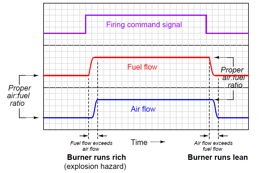
upset the air:fuel ratio during the times immediately following a step-change in firing command signal. When the firing command steps up, the fuel flow increases before the air flow, resulting in a short time when the burner runs “rich” (too much fuel, not enough air).
When the firing command steps down, the fuel flow decreases before the air flow, resulting in a short time when the burner runs “lean” (too much air, not enough fuel).
The scenario problem is dangerous because it may result in an explosion if an accumulation of unburnt fuel collects in a pocket of the combustion chamber and then ignites.
The second scenario is generally not a problem unless the flame burns so lean that it risks blowing out.
The solution to this vexing problem is to re-configure the control scheme so that the air flow controller “takes the lead” whenever the firing command signal rises, and that the fuel flow controller “takes the lead” whenever the firing command signal falls.
This way, any upsets in air:fuel ratio resulting from changes in firing command will always err on the side of a lean burn rather than a rich burn.
We may implement precisely this strategy by adding some signal selector functions to our ratio control system.
The ratio is now cross-limited, where both measured flow rates serve as limiting variables to each other to ensure the air:fuel ratio can never be too rich:
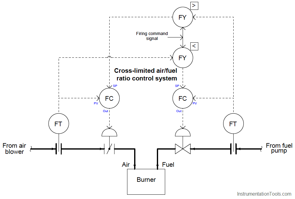
Now, the air flow controller receives its setpoint either directly from the firing command signal or from the fuel flow transmitter, whichever signal is greater in value.
The fuel flow controller receives its setpoint either directly from the firing command signal or from the air flow transmitter, whichever signal is least in value.
Thus, the air flow controller “takes the lead” and makes fuel flow the “captive” variable when the firing command signal rises. Conversely, the fuel flow controller “takes the lead” and makes air flow the “captive” variable when the firing command signal falls. Instead of having the roles of “wild” and “captive” flows permanently assigned, these roles switch depending on which way the firing command signal changes.
Examining the response of this cross-limited system to sudden changes in firing command signal, we see how the air flow controller takes the lead whenever the firing rate signal increases, and how the fuel flow controller takes the lead whenever the firing rate signal decreases:
In both transient scenarios, the mixture runs lean (safe) rather than rich (dangerous).
Of course, care must be taken to ensure the firing rate signal never steps up or down so quickly that the flame runs lean enough to blow out (i.e. the mixture becomes much too lean during a transient “step-change” of the firing rate signal). If this is a problem, we may fix it by installing rate-limiting functions in the firing command signal path, so that the firing command signal can never rise or fall too rapidly.
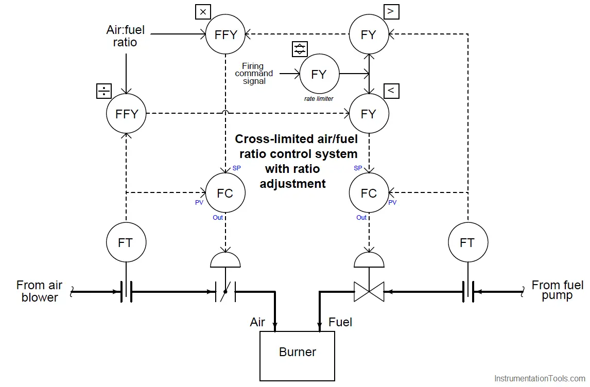
A realistic cross-limited ratio control system also incorporates a means to adjust the air:fuel ratio without having to re-range the air and/or fuel flow transmitters.
Such ratio adjustment may be achieved by the insertion of a “multiplying” function between one of the selectors and a controller setpoint, plus a “dividing” function to return that scaled flow to a normalized value for cross-limiting.
The complete control strategy looks something like this, complete with cross-limiting of air and fuel flows, rate-limiting of the firing command signal, and adjustable air:fuel ratio: