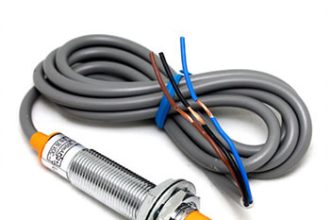
Proximity sensors and encoders can have NAMUR output
NAMUR is a type of sensor output that gives an on or off indication. There are different reasons why you may need a NAMUR sensor. I will go through some of them here.
First, some information about NAMUR. NAMUR is a German acronym for (normenarbeitsgemeinschaft für Mess- und Regeltechnik in der Chemischen Industrie). This translates to: Standardization Association for Measurement and Control in Chemical Industries. A NAMUR sensor is a non-amplified sensor that supplies two different signal levels depending upon switch state. These signal levels are low-level current. A logic interface circuit, controller, PLC, DCS, or intrinsically safe (IS) barrier is needed to read these current levels. A NAMUR output sensor is required in installations where special safety measures are necessary (locations with explosion hazard, or personal safety). The standards for NAMUR output sensors are EN 60947-5-6:2000 and IEC 60947-5-6:1999.
A NAMUR output sensor can be normally open or normally closed, but usually, it’s normally closed. This output is solid state, so there will be some current level on the output whether it’s on or off. When you look at a NAMUR output sensor data sheet, it will list nominal voltage (8.2 V), load (1 k ohm), and current for measuring plate detected (<1 mA) and not detected (>2.2 mA) (for normally closed output). Because of the low-current switching level, you’ll need an amplifier or an input that is designed specifically for NAMUR. Although the sensor may be able to handle a range of voltages (7 VDC to 12 VDC or 5 VDC to 25 VDC), the voltage level should be at 8.2 VDC with 1k ohm resistance as the load.
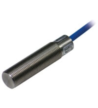
Proximity sensors and encoders can have NAMUR output. Some of the specific types of proximity sensors that have NAMUR output are capacitive, inductive, magnetic, and photoelectric sensors. Depending on the application, you could need any one of these products to detect your target, but if they meet the NAMUR standards, the output would be the same.
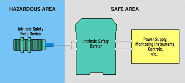
The NAMUR output products that have Ex ia (intrinsic safety) approvals can be installed in hazardous (classified) locations, such as Class I, II, III; Division 1, 2; and Zone 0, Zone 1, Zone 2 areas, as long as an approved intrinsically safe (IS) input or barrier is used with the NAMUR output product. The Zonal protection is usually for European and Class, Division is for North America. Some approval types are ATEX, FM, UL, IEC, CENELEC, TUV, PTB, and CSA.
Also Read: How to Select a Inductive Proximity Sensor
Prevention is the protection principle for intrinsic safety. It limits current so that the current is not capable of causing ignition in hazardous atmospheres. The other protection methods are containment (explosion-proof or flame-proof enclosure) andsegregation (purging, pressurization, encapsulation, or oil filled). Using intrinsic safety has its advantages: there are no special cables required or expensive explosion-proof conduit; it’s safe for personnel and suitable for all area classifications (Class I, II, III, Division 1, 2 and Zone 0, 1, 2).
If personal safety is needed, there are versions of the NAMUR output that are also fail-safe and have a SIL3 rating (with the appropriate amplifier). A fail-safe output ensures that if there is a failure, the output will sense a problem and fail only in the safe mode. With this NAMUR fail-safe output, you will also need the fail-safe-rated input or amplifier. This amplifier could be dual rated for personal safety and classified hazardous locations for gas, dust, or fibers. With this fail-safe sensor and amplifier, this “system” would have SIL3.
Usually, NAMUR output products (which include encoders and proximity sensors) are used in classified hazardous location areas which have explosive gas, dust, or fibers present. The fail-safe NAMUR output sensor is used where there is a personal safety hazard to protect personnel when they are working at or near the equipment. A fail-safe NAMUR version with the appropriate intrinsically/fail-safe barrier can provide both explosion hazard and personal safety protection.
Source : P & F