All transformers have copper and core losses. Copper loss is power lost in the primary and secondary windings of a transformer due to the ohmic resistance of the windings.
Copper loss, in watts, can be found using below Equation.
Copper Loss = IP2 RP + IS2 RS
where
IP = primary current
IS = secondary current
RP = primary winding resistance
RS = secondary winding resistance
Core losses are caused by two factors: hysteresis and eddy current losses. Hysteresis loss is that energy lost by reversing the magnetic field in the core as the magnetizing AC rises and falls and reverses direction.
Eddy current loss is a result of induced currents circulating in the core.
The efficiency of a transformer can be calculated using below Equations.
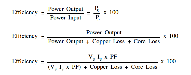
where
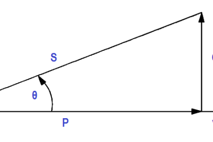
PF = power factor of the load
Example 1:
A 5:1 step-down transformer has a full-load secondary current of 20 amps. A short circuit test for copper loss at full load gives a wattmeter reading of 100 W. If RP = 0.3Ω, find RS and power loss in the secondary.
Solution :
Copper Loss = IP2 RP + IS2 RS = 100 W
To find IP
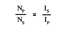
IP = (NS/NP) IS
IP = (1/5) 20 = 4 amps
To find RS
IS2 RS = 100 – IP2 RP
RS = (100 – IP2 RP ) / IS2
RS = (100 – 42 x 0.3 ) / 202
RS = 0.24
Power loss in secondary = IS2 RS = 202 x 0.24 = 96 W
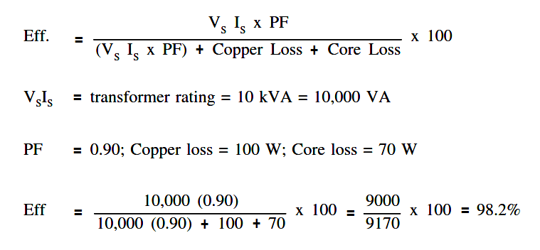
Example 2:
An open circuit test for core losses in a 10 kVA transformer gives a reading of 70 W. If the PF of the load is 90%, find efficiency at full load.
Solution :


How is transformer rating in kva?
Since Transformer doesnt produce any power rather than just only transform the Voltage and Current into high to low and low to high, for which Voltage and Ampere is related. Thats why its only rating in VA. and for larger transformer KVA and MVA is used for the rating of a transformer.
where did the copper loss of 100 W came from i the second problem?