Inst ToolsInst ToolsInst Tools
  • Courses
  • Automation
    • PLC
    • Control System
    • Safety System
    • Communication
    • Fire & Gas System
  • Instrumentation
    • Design
    • Pressure
    • Temperature
    • Flow
    • Level
    • Vibration
    • Analyzer
    • Control Valve
    • Switch
    • Calibration
    • Erection & Commissioning
  • Interview
    • Instrumentation
    • Electrical
    • Electronics
    • Practical
  • Q&A
    • Instrumentation
    • Control System
    • Electrical
    • Electronics
    • Analog Electronics
    • Digital Electronics
    • Power Electronics
    • Microprocessor
  • Request
Search
  • Books
  • Software
  • Projects
  • Process
  • Tools
  • Basics
  • Formula
  • Power Plant
  • Root Cause Analysis
  • Electrical Basics
  • Animation
  • Standards
  • 4-20 mA Course
  • Siemens PLC Course
Reading: Full-Wave Rectifier Circuit
Share
Notification Show More
Font ResizerAa
Inst ToolsInst Tools
Font ResizerAa
  • Courses
  • Design
  • PLC
  • Interview
  • Control System
Search
  • Courses
  • Automation
    • PLC
    • Control System
    • Safety System
    • Communication
    • Fire & Gas System
  • Instrumentation
    • Design
    • Pressure
    • Temperature
    • Flow
    • Level
    • Vibration
    • Analyzer
    • Control Valve
    • Switch
    • Calibration
    • Erection & Commissioning
  • Interview
    • Instrumentation
    • Electrical
    • Electronics
    • Practical
  • Q&A
    • Instrumentation
    • Control System
    • Electrical
    • Electronics
    • Analog Electronics
    • Digital Electronics
    • Power Electronics
    • Microprocessor
  • Request
Follow US
All rights reserved. Reproduction in whole or in part without written permission is prohibited.
Inst Tools > Blog > Electrical Theory > Full-Wave Rectifier Circuit

Full-Wave Rectifier Circuit

Last updated: July 22, 2018 11:03 pm
Editorial Staff
Electrical Theory
No Comments
Share
1 Min Read
SHARE

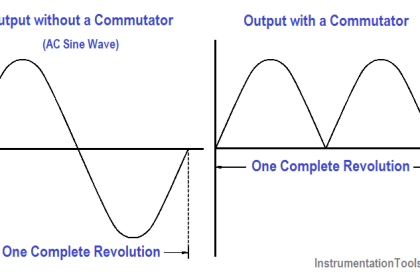
A full-wave rectifier circuit is a circuit that rectifies the entire cycle of the AC sine-wave. A basic full-wave rectifier uses two diodes. The action of these diodes during each half cycle is shown in Figure 7.

Center Tap Full-Wave Rectifier

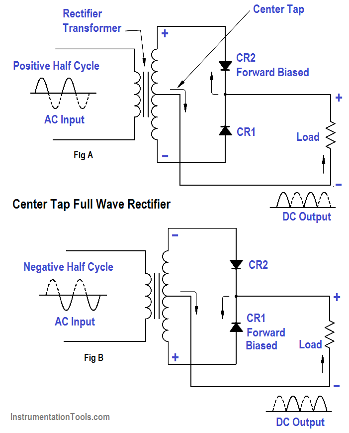
Figure 7 Full-Wave Rectifier

Another type of full-wave rectifier circuit is the full-wave bridge rectifier. This circuit utilizes four diodes. These diodes’ actions during each half cycle of the applied AC input voltage are shown in Figure 8. The output of this circuit then becomes a pulsating DC, with all of the waves of the input AC being transferred. The output looks identical to that obtained from a full-wave rectifier (Figure 7).

Bridge Rectifier Circuit

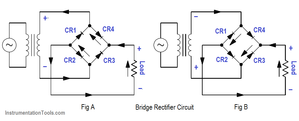
Figure 8 Bridge Rectifier Circuit

Don't Miss Our Updates
Be the first to get exclusive content straight to your email.
We promise not to spam you. You can unsubscribe at any time.
Invalid email address
You've successfully subscribed !

Continue Reading

Parallel AC Generators
Parallel Open Circuit Faults
Wiring Diagram
Types of AC Generators
High Voltage Circuit Breaker Principle
Conductor, Insulator, Resistor and Current Flow
Share This Article
Facebook Whatsapp Whatsapp LinkedIn Copy Link
Share
Leave a Comment

Leave a Reply Cancel reply

Your email address will not be published. Required fields are marked *

Stay Connected

128.3kFollowersLike
69.1kFollowersFollow
210kSubscribersSubscribe
38kFollowersFollow

Categories

Explore More

Voltage Polarity and Current Direction
AC Generator Voltage Regulators
Transformer Current Ratio
Units of Electrical Measurement
Applying Kirchhoff’s Voltage Law
Shunt-Wound DC Generators
Power Factor Meter Principle
Half-Wave Rectifier Circuit

Keep Learning

Shunt-Wound DC Motor

Shunt-Wound Motor Operation

Electric Short Circuit

Series Short Circuit Faults

LVR Motor Controller Operation

Low Voltage Protection (LVP) and Low Voltage Release (LVR)

Series-Wound DC Generator Principle

Series-Wound DC Generators

3-Wire, Three-Phase Delta Wiring System

3-Wire, Three-Phase Delta Wiring System

Electrical Symbols

Electrical Symbols

AC to DC Conversion with a Commutator

DC Machines Terminology

Types of Fuses

Electrical System Components and Protection Devices

Learn More

Power Electronics Objective Questions

Power Electronics Diode Circuits Questions and Answers

Heat Exchanger Differential Pressure Transmitter

Heat Exchanger Differential Pressure Transmitter

Stability in Frequency Domain

Nyquist Stability Criterion

Symbol of MOS Controlled Thyristor

MCT (MOS Controlled Thyristor) – Symbol, Working, Characteristics, Advantages

float-type level switch control a pump

Float-type Level Switch to Control a pump

Single-Phase Induction Motors Multiple Choice Questions (MCQ)

125+ Single-Phase Induction Motors Multiple Choice Questions (MCQ)

How PLC controls a ON-OFF Valve

PLC Valve Control Ladder Logic Programming

Thermocouples Green Rot Effect

Thermocouples Green Rot Effect

Menu

  • About
  • Privacy Policy
  • Copyright

Quick Links

  • Learn PLC
  • Helping Hand
  • Part Time Job

YouTube Subscribe

Follow US
All rights reserved. Reproduction in whole or in part without written permission is prohibited.
Welcome Back!

Sign in to your account

Username or Email Address
Password

Lost your password?