A power factor meter is a type of electrodynamometer movement when it is made with two movable coils set at right angles to each other. The method of connection of this type of power factor meter, in a 3φ circuit, is shown in Figure.
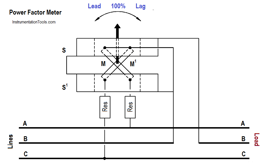
The two stationary coils, S and S1 , are connected in series in Phase B. Coils M and M1 are mounted on a common shaft, which is free to move without restraint or control springs. These coils are connected with their series resistors (Res) from Phase B to Phase A and from Phase B to Phase C.
At a power factor of unity, one potential coil current leads and one lags the current in Phase B by 30°; thus, the coils are balanced in the position shown in Figure.
A change in power factor will cause the current of one potential coil to become more in phase and the other potential coil to be more out of phase with the current in Phase B, so that the moving element and pointer take a new position of balance to show the new power factor.