Inst ToolsInst ToolsInst Tools
  • Courses
  • Automation
    • PLC
    • Control System
    • Safety System
    • Communication
    • Fire & Gas System
  • Instrumentation
    • Design
    • Pressure
    • Temperature
    • Flow
    • Level
    • Vibration
    • Analyzer
    • Control Valve
    • Switch
    • Calibration
    • Erection & Commissioning
  • Interview
    • Instrumentation
    • Electrical
    • Electronics
    • Practical
  • Q&A
    • Instrumentation
    • Control System
    • Electrical
    • Electronics
    • Analog Electronics
    • Digital Electronics
    • Power Electronics
    • Microprocessor
  • Request
Search
  • Books
  • Software
  • Projects
  • Process
  • Tools
  • Basics
  • Formula
  • Power Plant
  • Root Cause Analysis
  • Electrical Basics
  • Animation
  • Standards
  • 4-20 mA Course
  • Siemens PLC Course
Reading: AC Generator Voltage Regulators
Share
Font ResizerAa
Inst ToolsInst Tools
Font ResizerAa
  • Courses
  • Design
  • PLC
  • Interview
  • Control System
Search
  • Courses
  • Automation
    • PLC
    • Control System
    • Safety System
    • Communication
    • Fire & Gas System
  • Instrumentation
    • Design
    • Pressure
    • Temperature
    • Flow
    • Level
    • Vibration
    • Analyzer
    • Control Valve
    • Switch
    • Calibration
    • Erection & Commissioning
  • Interview
    • Instrumentation
    • Electrical
    • Electronics
    • Practical
  • Q&A
    • Instrumentation
    • Control System
    • Electrical
    • Electronics
    • Analog Electronics
    • Digital Electronics
    • Power Electronics
    • Microprocessor
  • Request
Follow US
All rights reserved. Reproduction in whole or in part without written permission is prohibited.
Inst Tools > Blog > Electrical Theory > AC Generator Voltage Regulators

AC Generator Voltage Regulators

Last updated: August 5, 2018 9:41 pm
Editorial Staff
Electrical Theory
No Comments
Share
5 Min Read
SHARE

Because the voltage from an AC generator varies as the output load and power factor change, a voltage regulator circuit is necessary to permit continuity of the desired output voltage.

Purpose

The purpose of a voltage regulator is to maintain the output voltage of a generator at a desired value. As load on an AC generator changes, the voltage will also tend to change. The main reason for this change in voltage is the change in the voltage drop across the armature winding caused by a change in load current. In an AC generator, there is an IR drop and an IXL drop caused by the AC current flowing through the resistance and inductance of the windings.

The IR drop is dependent on the amount of the load change only. The IXL drop is dependent on not only the load change, but also the power factor of the circuit. Therefore, the output voltage of an AC generator varies with both changes in load (i.e., current) and changes in power factor. Because of changes in voltage, due to changes in load and changes in power factor, AC generators require some auxiliary means of regulating output voltage.

Block Diagram Description

The below Figure shows a typical block diagram of an AC generator voltage regulator. This regulator consists of six basic circuits that together regulate the output voltage of an AC generator from no-load to full-load.

AC generator Voltage Regulators

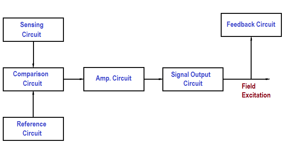
Figure : Voltage Regulator Block Diagram

Sensing Circuit

The sensing circuit senses output voltage of the AC generator. As the generator is loaded or unloaded, the output voltage changes, and the sensing circuit provides a signal of these voltage changes. This signal is proportional to output voltage and is sent to the comparison circuit.

Reference Circuit

The reference circuit maintains a constant output for reference. This reference is the desired voltage output of the AC generator.

Comparison Circuit

The comparison circuit electrically compares the reference voltage to the sensed voltage and provides an error signal. This error signal represents an increase or decrease in output voltage. The signal is sent to the amplification circuit.

Amplification Circuit

The amplification circuit, which can be a magnetic amplifier or transistor amplifier, takes the signal from the comparison circuit and amplifies the milliamp input to an amp output, which is then sent to the signal output, or field, circuit.

Signal Output Circuit

The signal output circuit, which controls field excitation of the AC generator, increases or decreases field excitation to either raise or lower the AC output voltage.

Feedback Circuit

The feedback circuit takes some of the output of the signal output circuit and feeds it back to the amplification circuit. It does this to prevent overshooting or undershooting of the desired voltage by slowing down the circuit response.

Changing Output Voltage

Let us consider an increase in generator load and, thereby, a drop in output voltage. First, the sensing circuit senses the decrease in output voltage as compared to the reference and lowers its input to the comparison circuit. Since the reference circuit is always a constant, the comparison circuit will develop an error signal due to the difference between the sensed voltage and the reference voltage.

The error signal developed will be of a positive value with the magnitude of the signal dependent on the difference between the sensed voltage and the reference voltage. This output from the comparison circuit will then be amplified by the amplifier circuit and sent to the signal output circuit. The signal output circuit then increases field excitation to the AC generator. This increase in field excitation causes generated voltage to increase to the desired output.

If the load on the generator were decreased, the voltage output of the machine would rise. The actions of the voltage regulator would then be the opposite of that for a lowering output voltage. In this case, the comparison circuit will develop a negative error signal whose magnitude is again dependent on the difference between the sensed voltage and the reference voltage. As a result, the signal output circuit will decrease field excitation to the AC generator, causing the generated voltage to decrease to the desired output.

Don't Miss Our Updates
Be the first to get exclusive content straight to your email.
We promise not to spam you. You can unsubscribe at any time.
Invalid email address
You've successfully subscribed !

Continue Reading

Types of Capacitors
Series Resistance
Magnetic Circuits
Generator Action in a Motor
Induction Motor Torque Versus Slip
DC Circuit Analysis Node Equations
Share This Article
Facebook Whatsapp Whatsapp LinkedIn Copy Link
Share
Leave a Comment

Leave a Reply Cancel reply

Your email address will not be published. Required fields are marked *

Stay Connected

128.3kFollowersLike
69.1kFollowersFollow
210kSubscribersSubscribe
38kFollowersFollow

Categories

Explore More

Three Phase Transformer Connections
Classification of Transformers
Electrical Wiring Terminology
DC Motor Connections
Capacitance and Capacitive Reactance
Transformer Impedance Ratio
Parallel Short Circuit Faults
Discharge and Charging of Lead-Acid Battery

Keep Learning

Inductor Principle

Inductor

Electrodynamometer Movement Principle

Electro-Dynamo Meter Movement

Transformer Efficiency

Transformer Efficiency

Simple RC Circuit

Impedance in RC Circuits

Split Phase Motor

Single Phase AC Induction Motors

Forward Bias

Rectifiers, Forward Bias and Reverse Bias

How to Measure Specific Gravity of Battery

How to Measure Specific Gravity of Battery

Batteries Connected in Parallel

Battery Operation : Series and Parallel

Learn More

Address Overlapping in Tia Portal

How to Check Address Overlapping in Tia Portal?

Intelligent Motor Control Center

What is an Intelligent Motor Control Center? – IMCC

Difference Between PLC and SCADA

Difference Between PLC and SCADA

Serial Communication Interview Questions

Serial Communication Interview Questions and Answers

Remote Capillary Level Transmitter Mounted below the Zero Level

How to Calculate mmWC Range of Level Transmitter with Examples?

Analyzer chopper wheel

NDIR Analyzer Filter Cells

Linear to Square Root Extraction

How to Link SQL With Indusoft Web Studio

How to Use an SQL Server with Indusoft Web Studio?

Menu

  • About
  • Privacy Policy
  • Copyright

Quick Links

  • Learn PLC
  • Helping Hand
  • Part Time Job

YouTube Subscribe

Follow US
All rights reserved. Reproduction in whole or in part without written permission is prohibited.
Welcome Back!

Sign in to your account

Username or Email Address
Password

Lost your password?