Inst ToolsInst ToolsInst Tools
  • Courses
  • Automation
    • PLC
    • Control System
    • Safety System
    • Communication
    • Fire & Gas System
  • Instrumentation
    • Design
    • Pressure
    • Temperature
    • Flow
    • Level
    • Vibration
    • Analyzer
    • Control Valve
    • Switch
    • Calibration
    • Erection & Commissioning
  • Interview
    • Instrumentation
    • Electrical
    • Electronics
    • Practical
  • Q&A
    • Instrumentation
    • Control System
    • Electrical
    • Electronics
    • Analog Electronics
    • Digital Electronics
    • Power Electronics
    • Microprocessor
  • Request
Search
  • Books
  • Software
  • Projects
  • Process
  • Tools
  • Basics
  • Formula
  • Power Plant
  • Root Cause Analysis
  • Electrical Basics
  • Animation
  • Standards
  • 4-20 mA Course
  • Siemens PLC Course
Reading: Induction Motor Torque Versus Slip
Share
Font ResizerAa
Inst ToolsInst Tools
Font ResizerAa
  • Courses
  • Design
  • PLC
  • Interview
  • Control System
Search
  • Courses
  • Automation
    • PLC
    • Control System
    • Safety System
    • Communication
    • Fire & Gas System
  • Instrumentation
    • Design
    • Pressure
    • Temperature
    • Flow
    • Level
    • Vibration
    • Analyzer
    • Control Valve
    • Switch
    • Calibration
    • Erection & Commissioning
  • Interview
    • Instrumentation
    • Electrical
    • Electronics
    • Practical
  • Q&A
    • Instrumentation
    • Control System
    • Electrical
    • Electronics
    • Analog Electronics
    • Digital Electronics
    • Power Electronics
    • Microprocessor
  • Request
Follow US
All rights reserved. Reproduction in whole or in part without written permission is prohibited.
Inst Tools > Blog > Electrical Theory > Induction Motor Torque Versus Slip

Induction Motor Torque Versus Slip

Last updated: August 6, 2018 4:06 pm
Editorial Staff
Electrical Theory
No Comments
Share
2 Min Read
SHARE

The torque of an AC induction motor is dependent upon the strength of the interacting rotor and stator fields and the phase relationship between them.

Torque can be calculated by using below Equation.

T = K Φ IR cos θR

where

Τ = torque (lb-ft)
K = constant
Φ = stator magnetic flux
IR = rotor current (A)
cos θR = power factor of rotor

During normal operation, K, Φ, and cos θR are, for all intents and purposes, constant, so that torque is directly proportional to the rotor current. Rotor current increases in almost direct proportion to slip. The change in torque with respect to slip (Below Figure) shows that, as slip increases from zero to ~10%, the torque increases linearly.

As the load and slip are increased beyond full-load torque, the torque will reach a maximum value at about 25% slip. The maximum value of torque is called the breakdown torque of the motor. If load is increased beyond this point, the motor will stall and come to a rapid stop.

The typical induction motor breakdown torque varies from 200 to 300% of full load torque. Starting torque is the value of torque at 100% slip and is normally 150 to 200% of full-load torque. As the rotor accelerates, torque will increase to breakdown torque and then decrease to the value required to carry the load on the motor at a constant speed, usually between 0-10%.

induction motor torque versus speed

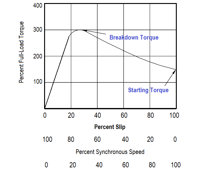
Figure : Torque vs Slip

Don't Miss Our Updates
Be the first to get exclusive content straight to your email.
We promise not to spam you. You can unsubscribe at any time.
Invalid email address
You've successfully subscribed !

Continue Reading

DC Machines Construction
Shunt-Wound Motor Operation
Transformer Theory of Operation
Single Phase Power Wiring Schemes
Resistivity
Parallel Open Circuit Faults
Share This Article
Facebook Whatsapp Whatsapp LinkedIn Copy Link
Share
Leave a Comment

Leave a Reply Cancel reply

Your email address will not be published. Required fields are marked *

Stay Connected

128.3kFollowersLike
69.1kFollowersFollow
210kSubscribersSubscribe
38kFollowersFollow

Categories

Explore More

Block Diagram
Battery Hazards
Ampere Hour Meter
Ammeter
Series Circuit
Parallel AC Generators
Calculate Power in Parallel RL Circuit
Current Division

Keep Learning

Compounded DC Generator

Compound Generators

Power Factor Meter Principle

Power Factor Meter Principle

Thermocouples

Thermocouples

Ohm Meter Circuit

Ohm Meter

Megger Circuit Diagram

Multimeter & Megger Principle

Generator Action in a Motor

Generator Action in a Motor

Marking Polarity

DC Circuit Analysis Loop Equations

LVR Motor Controller Operation

Low Voltage Protection (LVP) and Low Voltage Release (LVR)

Learn More

Gearbox within week Failing Journal Bearing upset Plant Operations

Gearbox within week Failing Journal Bearing upset Plant Operations

How to Activate the Schneider PLC Software License

How to Download EcoStruxure Machine Expert? Schneider PLC Software

Air Pressure Regulator cut-away diagram

Air Pressure Regulator Questions

Discrete Manufacturing Automation

Discrete Manufacturing Automation

Foundation Fieldbus Segment Topology

Foundation Fieldbus (FF) Segment Topology

Preventive Maintenance of Variable Frequency Drive

Preventive Maintenance of Variable Frequency Drive (VFD)

Basic Temperature Sensors MCQ

Basic Temperature Sensors MCQ Questions Answers

Machine Tool and Coolant Control PLC Ladder Logic

Machine Tool and Coolant Control: PLC Ladder Logic Design

Menu

  • About
  • Privacy Policy
  • Copyright

Quick Links

  • Learn PLC
  • Helping Hand
  • Part Time Job

YouTube Subscribe

Follow US
All rights reserved. Reproduction in whole or in part without written permission is prohibited.
Welcome Back!

Sign in to your account

Username or Email Address
Password

Lost your password?