In previous articles, we talked about timers in PLC, different types, and how to use them. Timers don’t really need real-time to work, as they just depend on counting seconds or milliseconds depending on your settings.
But for some applications, you need to know the PLC program’s real date and time for example for diagnostics purposes.
In this article, we will talk about the system and local time of a PLC.
Contents:
- Why do I need real-time in PLC?
- Example program and simulation
- What is system time?
- What is local time?
- Conclusions.
Why do I need Real-time in PLC?
In many applications of PLCs, you would need to know the real-time while the process is running, for many different reasons.
Following are some of these reasons:
- Backup of the PLC to the main server.
- For diagnostics of the PLC, you need to have a time record for the diagnostics, to know at which time a certain event has occurred, otherwise, diagnostics information wouldn’t be very useful.
- For applications where you need to work with the time of day interrupts OB10 you would need to know the actual time.
- You might need to use local time or system time in parts of your logic where you need to handle real-time applications.
- For data logging, if you have important data to save and you need the time stamp for each data recording, then you need to have the right time setting for your PLC so that stored data would make sense.
PLC Example Program and Simulation
To better understand what is system time and local time in a PLC, we will start by creating a very simple program and use it to explain the concept of real times inside PLCs.
Check the following step:
In this article, we will not create any PLC logic, but we will show some configurations that are related to the system and local time in PLC, how to set them, and what are the differences.
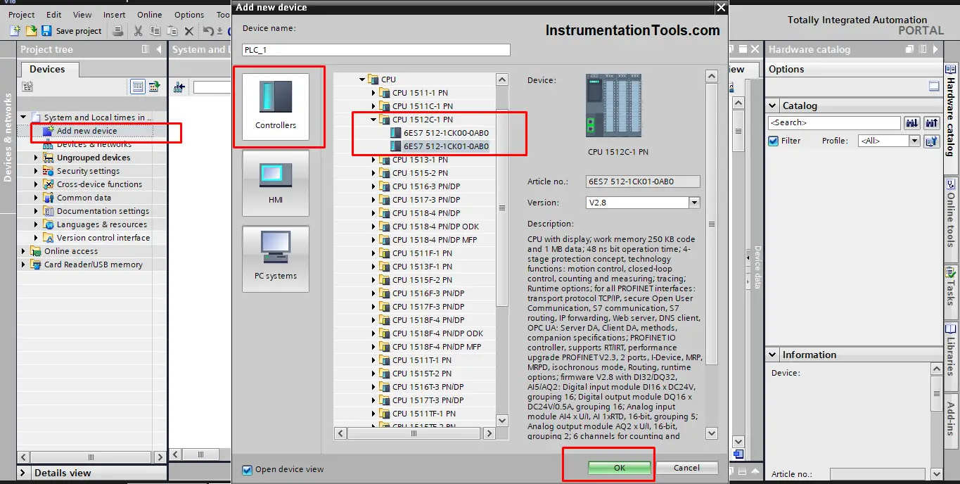
Open Siemens Tia Portal, Add a new device, and this time we will use the CPU 1512C-1 PN. See picture 1.
Compile and start a new PLC simulation. open the online & diagnostics page and check the set time of the PLC. See picture 2.
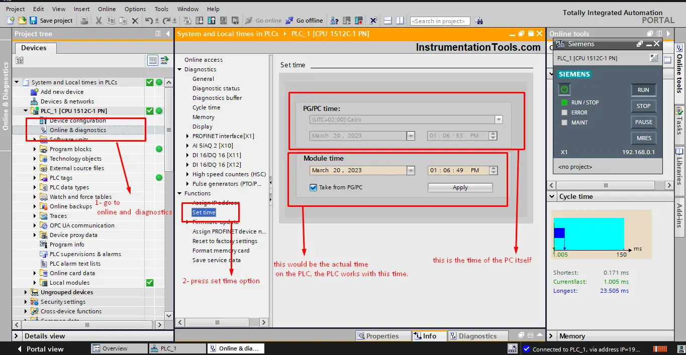
From the previous picture you can see that there are two different times:
- The PG/PC time – this is the local time of your PC itself.
- The Module time – this is the actual time inside the PLC itself.
Both these times can be set as the same value, or they can be different. it is best to make them the same, it is better to make the module time similar to your local time, or more specifically similar to the local time of the area where the PLC will be used. See picture 3.
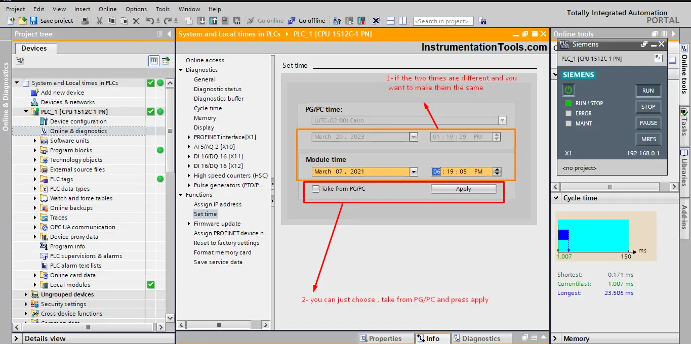
If you want module time to be the same as local time, then select Take from PG/PC and press apply.
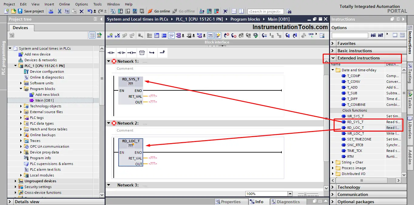
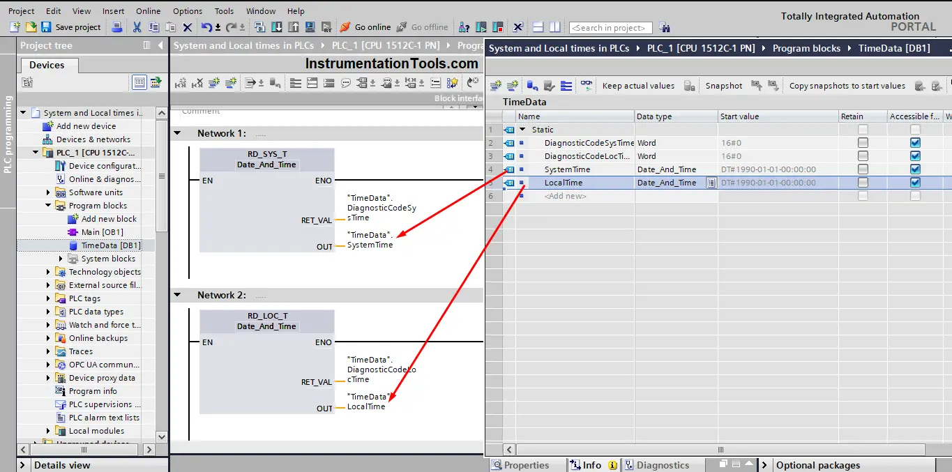
In your main OB1, drag and drop the RD_SYS_T and RD_LOC_T instructions.
These are the read system time and read local time instructions. These instructions are built-in functions FCs inside the PLC and they are used to write the local time and system time of the PLC to whichever destination you choose in the output OUT of the instruction. see picture 4.
Add a new global data block, and define some tags to work with. See picture 5.
Run your simulation again and check both times. See pictures 6
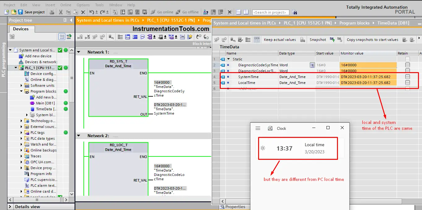
You see from the previous picture that the local time and system time of the PLC is the same, but they are different from the actual local time of your PC.
If you remember, we have set the module time of the PLC to be similar to the PG/PC time, which is your local time. See picture 7.
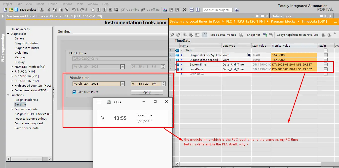
As you see, on the set time page the module time is chosen to be taken from PG/PC time. But then in actual cases, they are different. Why?
Why times are different? Because the default setting of the PLC local time is the UTC+0 or the Zulu time if you’re familiar with that term, you don’t change it from the online and diagnostics page, but rather from the properties of the PLC itself. See picture 8.
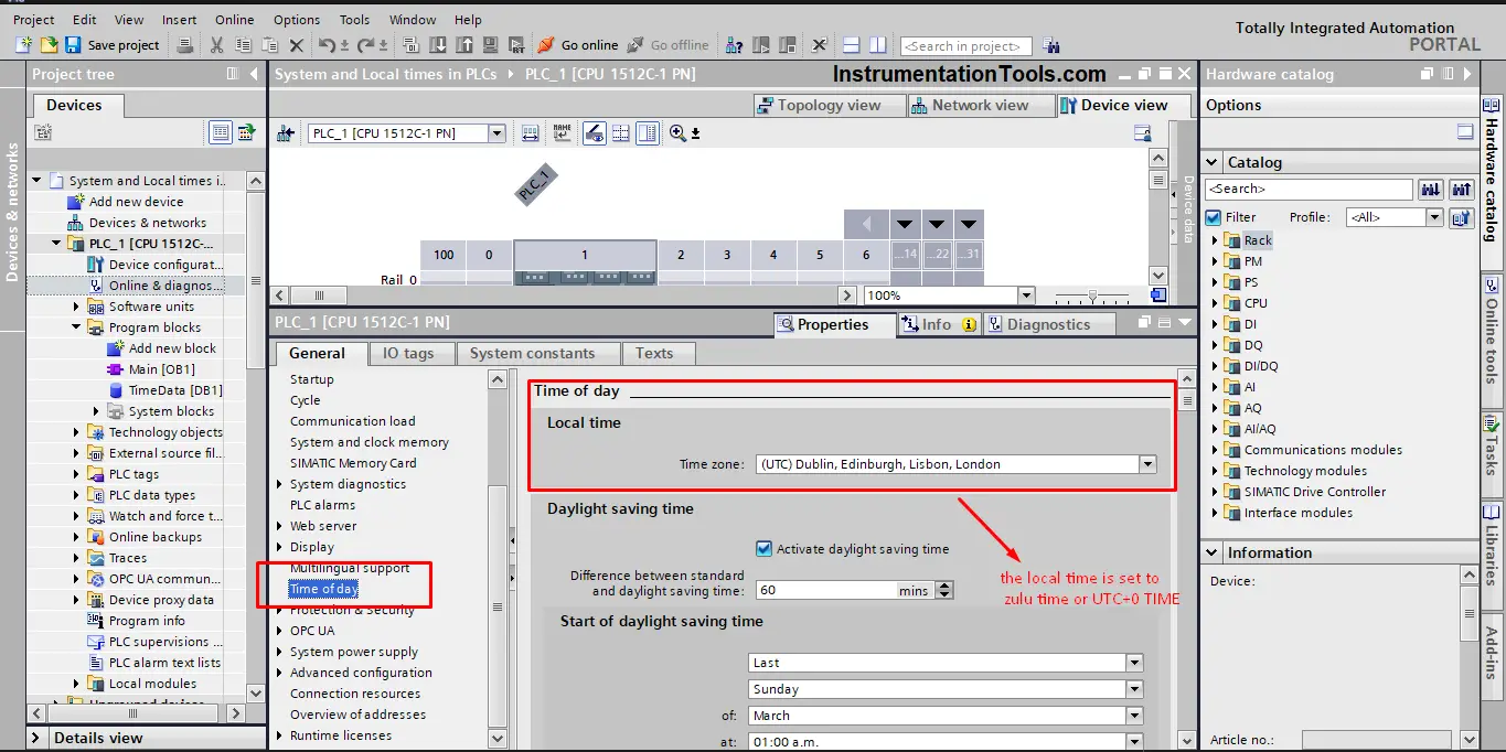
As you can see, the default setting of the PLC time of day is set to UTC+0 time, and that is why the PLC module time was different from your actual local time. Except if you were actually in London, then you wouldn’t face this problem.
To correct the PLC local time we have to change that in the configuration, we need to change the time zone to the time zone we have, which is in my case the UTC+02:00. See picture 9.
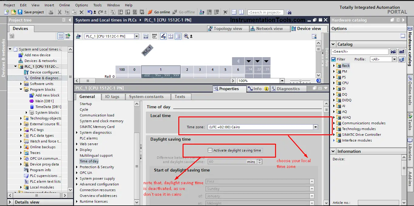
You can also see that the daylight saving time option was deactivated because it is not used in my country. You will have to activate it if it is used in your area.
Now that all configurations are set correctly, go back and see the local time and system time again in the simulation. See picture 10.
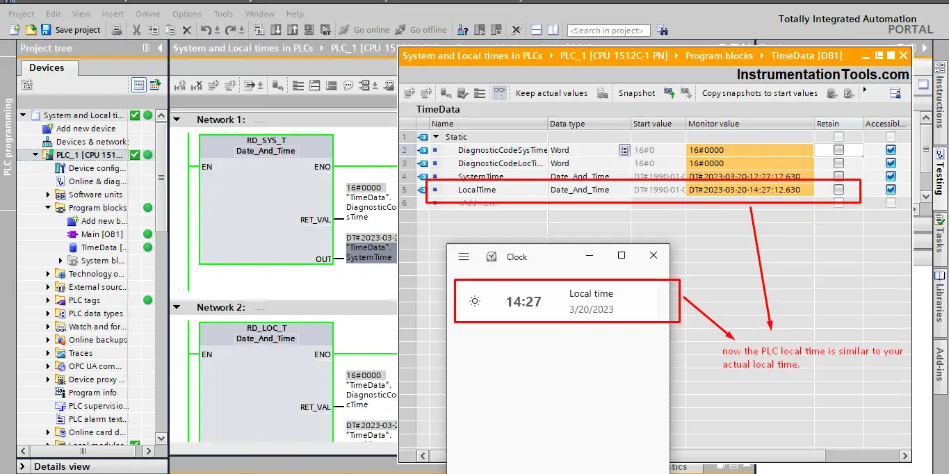
You see now after adjusting the PLC time zone, the local time of the PLC and the actual local time of your area is the same.
As we said before it is very important to set the right local time of the PLC, for the many reasons we mentioned above. Can you now define what is the system time and local time of the PLC?
System Time in PLC
Is the module time of the CPU clock.
The CPU clock interprets the module time as the coordinated universal time (UTC). Accordingly, the module time is always stored without the factors “local time zone” or “summer time” in the CPU clock. The CPU clock then calculates the local time of the CPU clock based on the module time.
The module time of the CPU clock is used as a template for all time processes starting from the CPU.
Examples of use:
- Calculation of local time of CPU clock based on module time
- Representation of the module time in local time under “Online & Diagnostics”
- Entries in the diagnostics buffer of the CPU
Local Time in PLC
Information on the time zone and the start of daylight saving time and standard time, which you have set in the configuration of the CPU clock, is used to output the local time.
Local time is the time you have on your PC or in your country which will be different from one area to another.
Downloads:
Conclusion
Many applications will require that the PLC would know the real-time or local time of the process, so that it would be able to perform certain tasks, for example, data logging and diagnostics tasks. In a future article, we will show some applications where real-time is needed for your logic
The local time of the PLC should be manually configured to match the area where the PLC will be used.
If you liked this article, then please subscribe to our YouTube Channel for Instrumentation, Electrical, PLC, and SCADA video tutorials.
You can also follow us on Facebook and Twitter to receive daily updates.
Read Next:
- SCADA System Architecture
- Function Blocks in PLC Program
- Two Hand Press Control Circuit
- Safety PLC Programming Practices
- Feedback Monitoring in Safety PLC