In the previous article, we talked about faceplates and we showed how to create, edit, and connect our faceplate to the PLC project. We showed how using faceplates in your HMI project can make it very easy and fast to design visualization for multiple similar systems. In this article, we will show how using UDTs with faceplates can even provide more flexibility and ease to your PLC project.
Contents:
- Using faceplates with too many instances.
- Reminder of UDTs.
- Implement UDTs with faceplates
- Edit the UDT in the global library
- Conclusions.
Using faceplates with too many instances
In previous articles, we showed how faceplates can be very useful in minimizing the time and effort you would consume to design and create a visualization of multiple numbers of the same system.
Faceplates are designed to act as a standardized visualization that I can call and apply when I have multiple numbers of the same system. each time I call and use a faceplate it is called an instance, and I can use as many instances as I would like in my project.
Each time I use a faceplate instance, I have to connect this instance to the corresponding system that is used. For example, we created a faceplate for a tank system, and each time we use an instance for a tank we have to connect the faceplate interface to the tank in use. See picture 1.
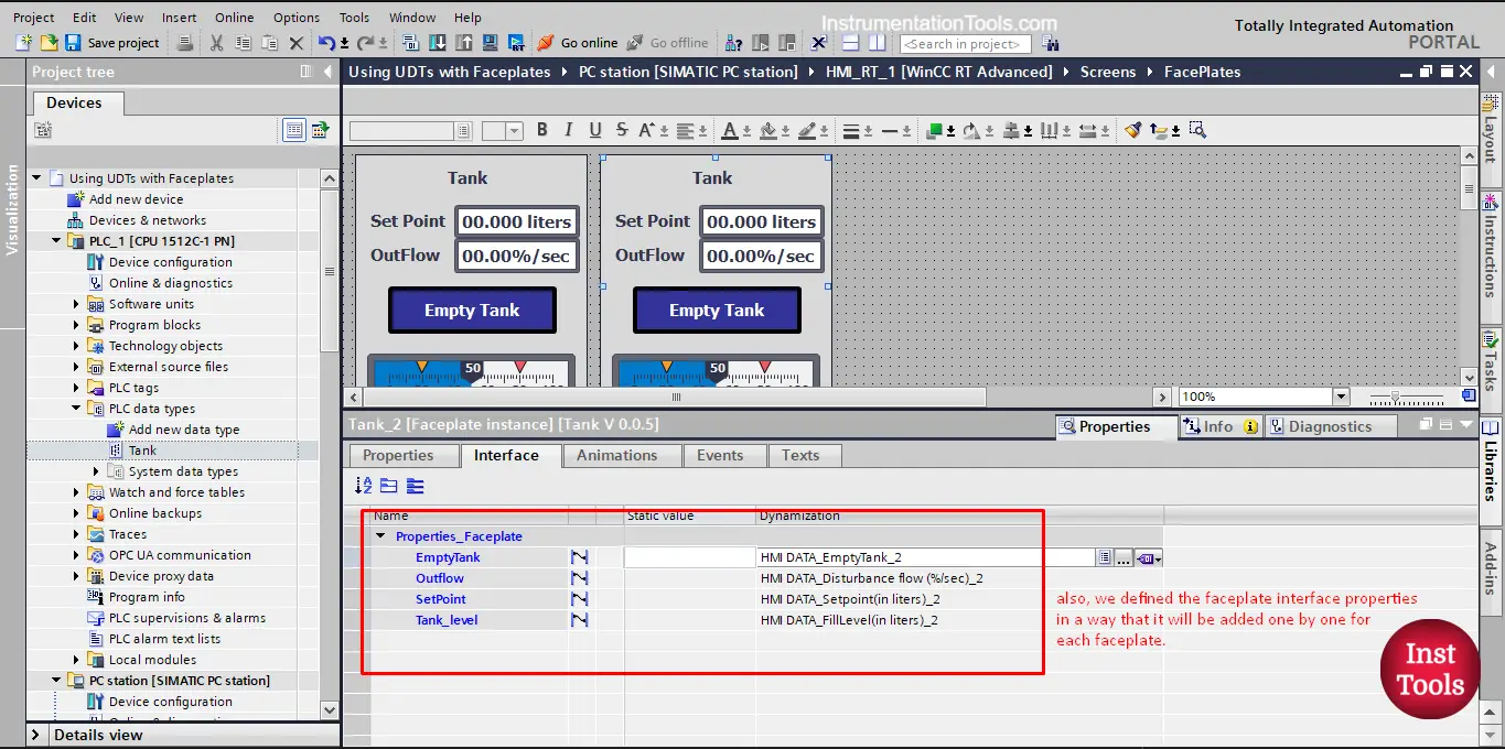
Picture 1. Faceplate instance for Tank_2
As you can see, with Tank_2 we provided the tags of that tank and if we used another instance for another tank, we will provide the tags for that tank also. This made the visualization part very simple and fast as I just have to drag and drop a new instance each time I have a new tank.
However, if my system has a large number of tanks, this will mean that I have to define an equal number of tags for these tanks and I have to connect each faceplate with the tags of its tank. This is where UDTs can be very helpful and useful.
Reminder of UDTs (User-Defined Data Types)
We showed before in previous articles what UDTs are, and how we can create a UDT in our project. We created a UDT for our tank system that has all the needed and related tags to a tank.
Whenever I have a tank system in my PLC project, I would just define a new Tank tag and make it of the UDT type we created. See picture 2.
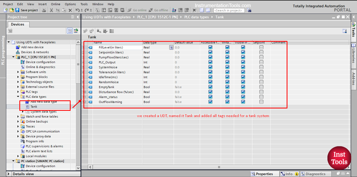
picture 2. Tank UDT that we define.
Implement UDTs with faceplates
To make any change to our faceplate, we have to open a new version of that faceplate, to do so, just right-click the faceplate and press edit faceplate. See picture 3.
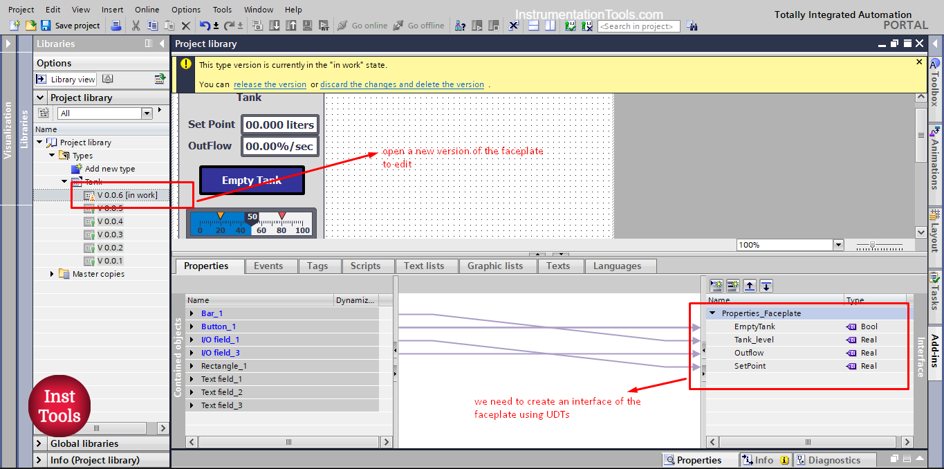
picture 3. Edit the faceplate.
To implement UDTs in our faceplate, we have to create the interface of our faceplate using the UDT instead of the individual tags that we used before.
As you see from the previous picture. To do that we will add a new property, name it Tank, and give the data type of the Tank UDT we created. See picture 4.
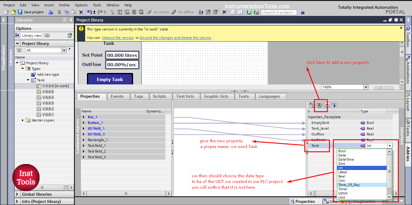
picture 4. Add a new property of data type Tank.
The first thing you will notice is that you can’t find the data type Tank in the current list. This is because the Tank UDT we created is only defined for our PLC project and not for the HMI project. See picture 5.
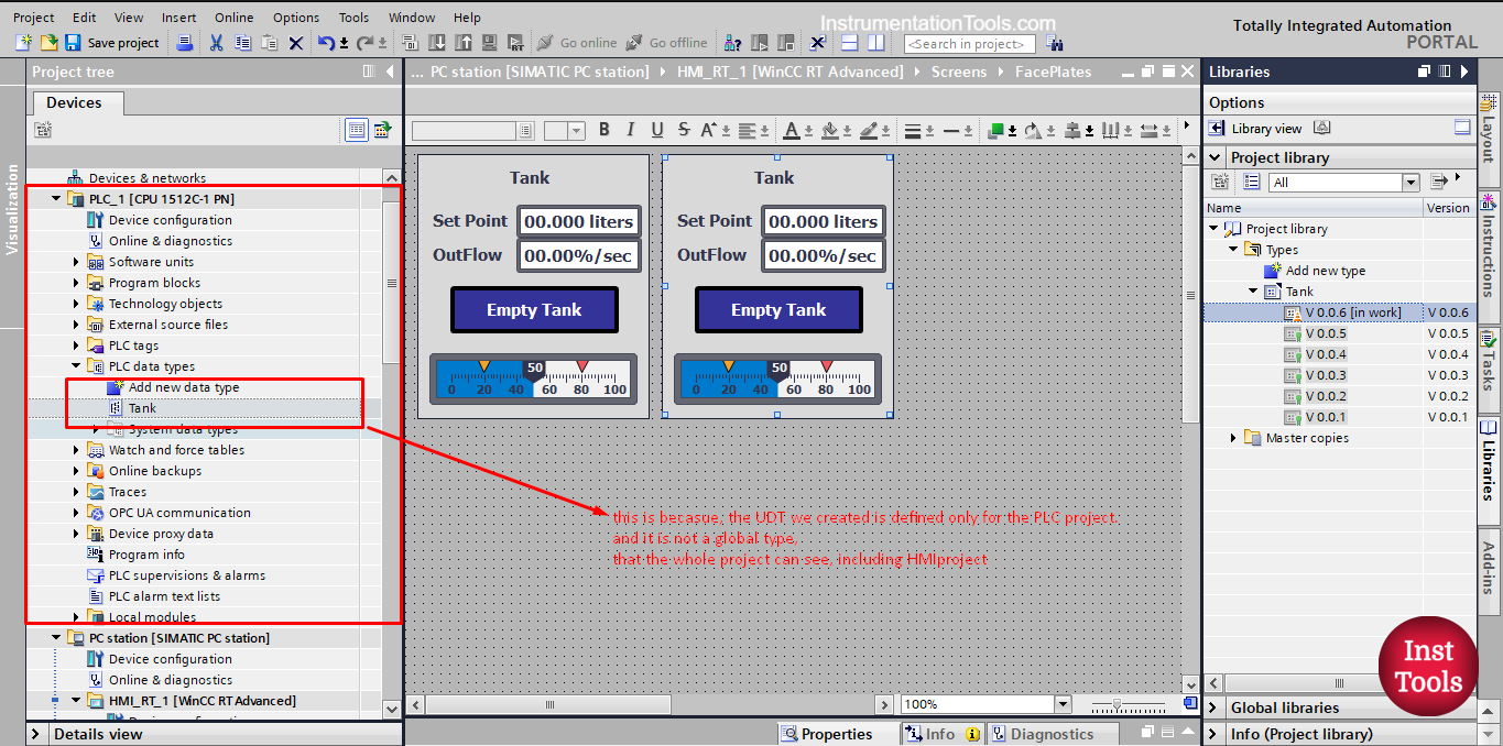
picture 5. UDT is only defined for the PLC.
To be able to use the UDT type in our HMI project, we have to make the UDT a global type that will be defined globally and can be used within the HMI project as well.
To do so, we just drag and drop our UDT into the TYPES folder in the project library. See picture 6.
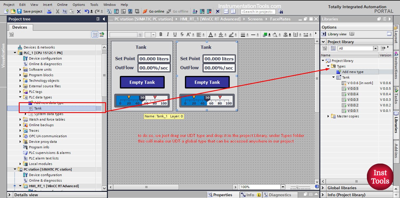
picture 6. Drag and drop the UDT in the project library.
Once we do that, an add type window will appear, because our faceplate name is Tank, we can’t give the UDT the Tank name, so we will give it a different name, see picture 7.
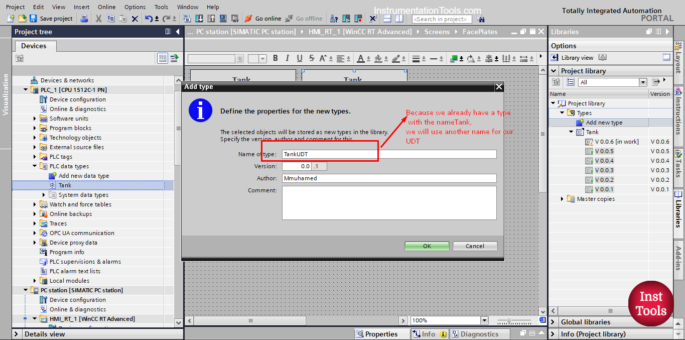
picture 7. Choose a proper name for the UDT type.
Once you press OK the UDT tank will be a global type and we can use it in our faceplate. See picture 8.
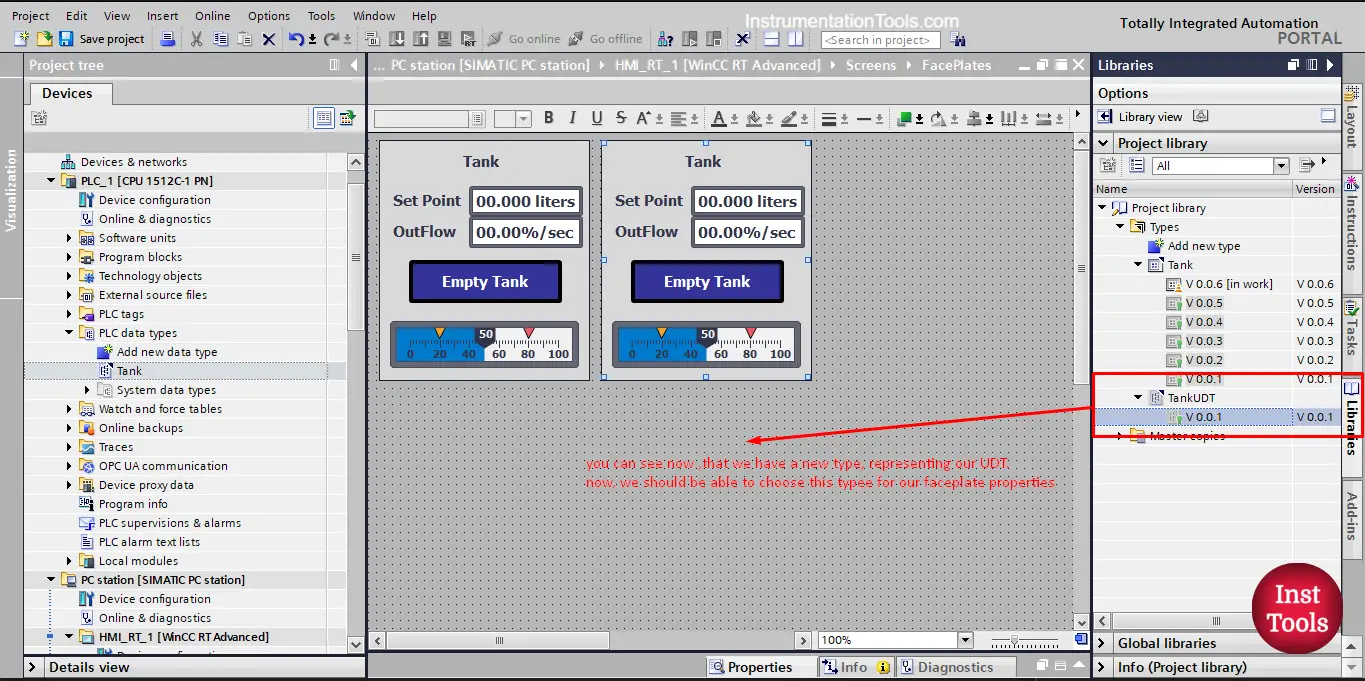
picture 8. Global UDT type.
As you can see, the UDT is now a type in your project with a version V0.0.1 and now we can use it with our faceplate. See picture 9.
picture 9. We now can find the UDT.
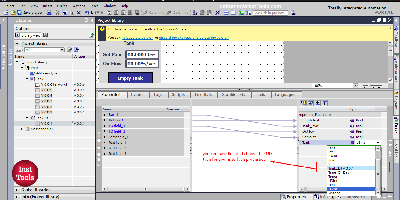
Now, we can find and select the UDT data type for the new property that we created for our faceplate.
Once it is added you will find all the internal tags of the UDT already defined within this Tank property. See picture 10.
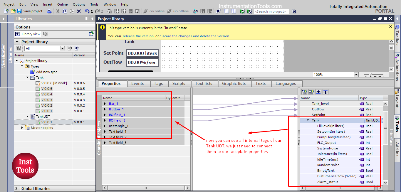
picture 10. Internal tags of the Tank UDT.
We now need to connect our faceplate properties to the internal tags of the UDT property. But first, let’s delete the old properties that we created before, as we don’t need them now. See picture 11.
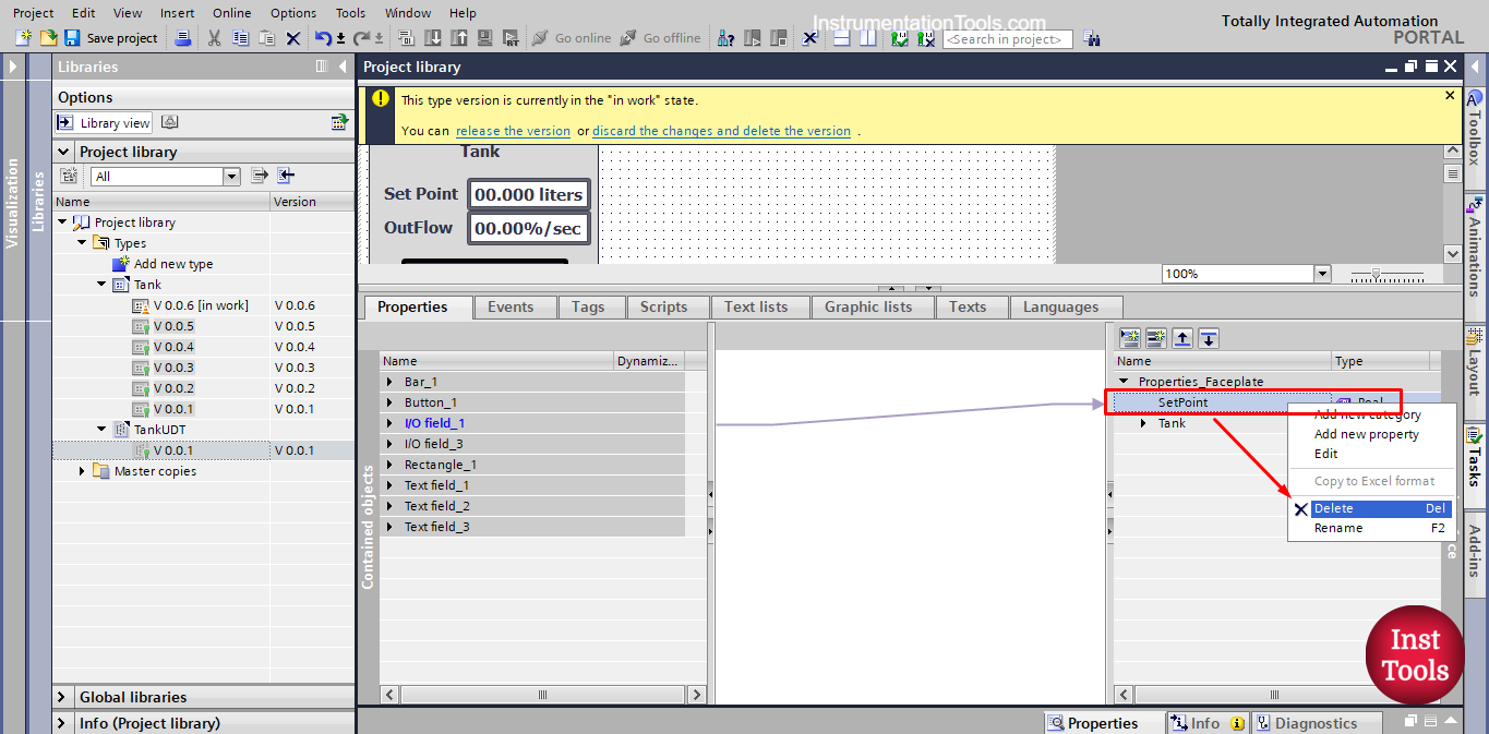
picture 11. Delete old properties of the faceplate.
Now, we connect the faceplate elements properties to our interface as we did before, by drag and drop.
For example, the set point I/O field process value is connected to the Tank UDT set point tag by dragging and dropping as we showed before. See picture 12.
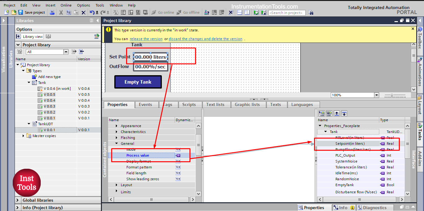
picture 12. Set point process value.
For the Empty Tank button, don’t forget to an event for the button, while the button is pressed, the empty tank tag inside the PLC should be set to 1. See picture 13.
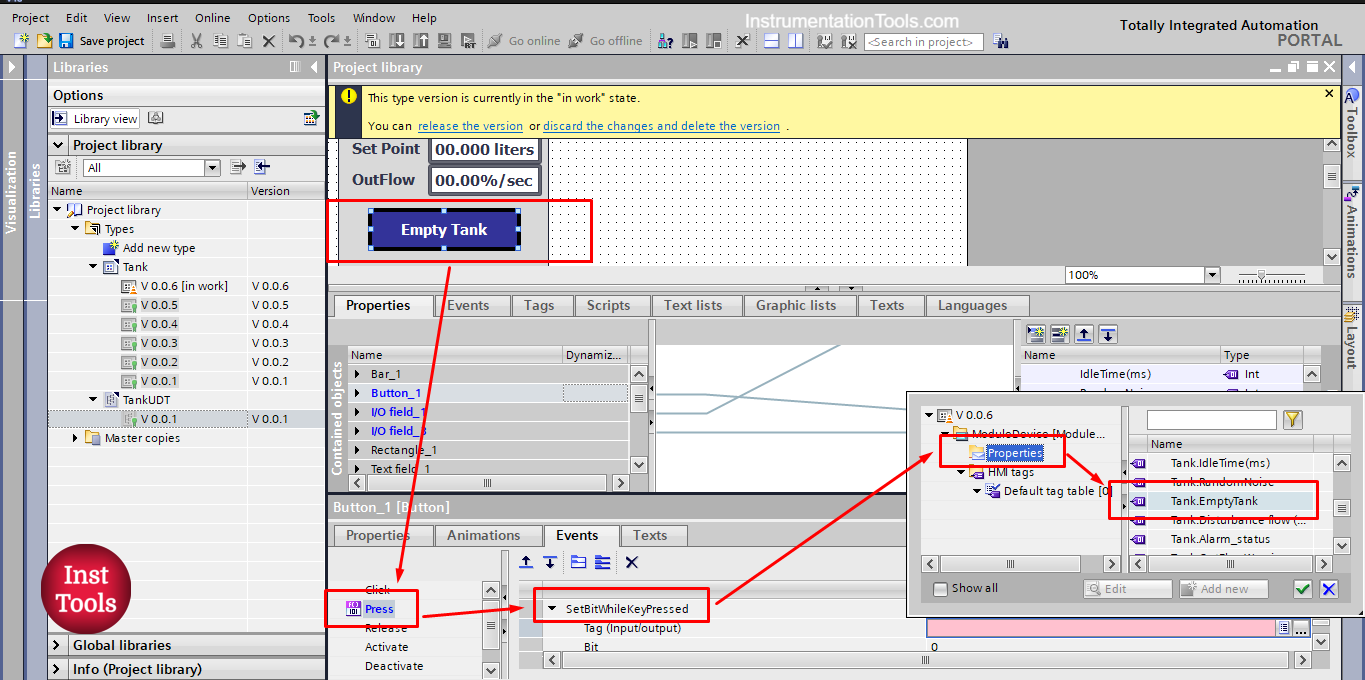
picture 13. Empty tank button event configuration.
After you connect all faceplate properties, we need to release the faceplate version to apply the changes we made.
Also don’t forget to update instances in the project as well. See pictures 14 and 15.
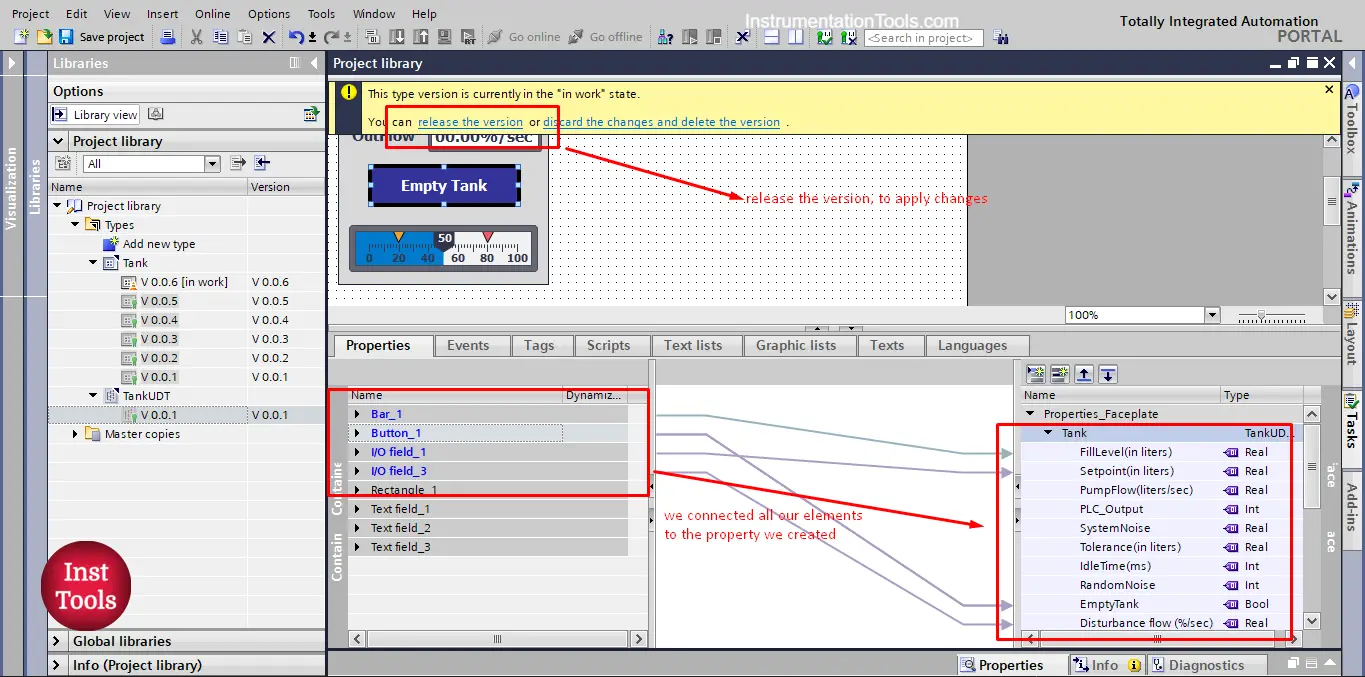
picture 14. Release the faceplate version.
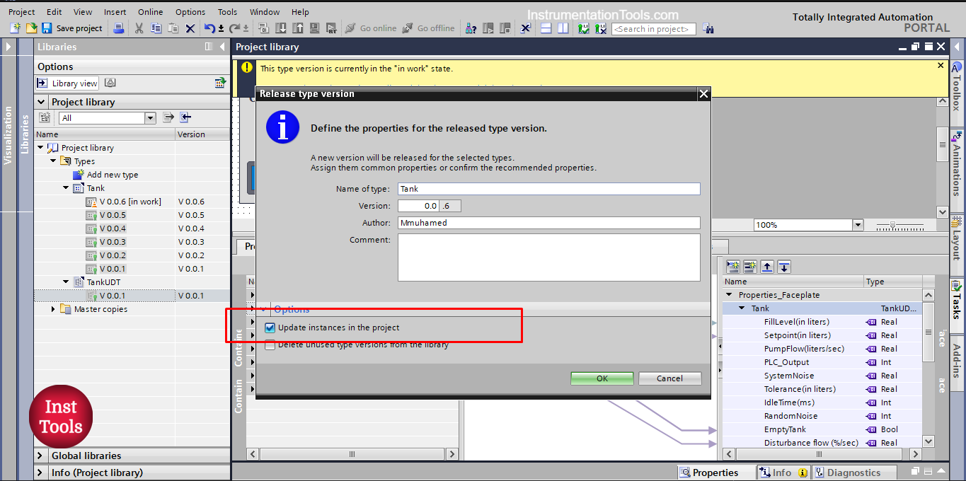
picture 15. Update instances in the project.
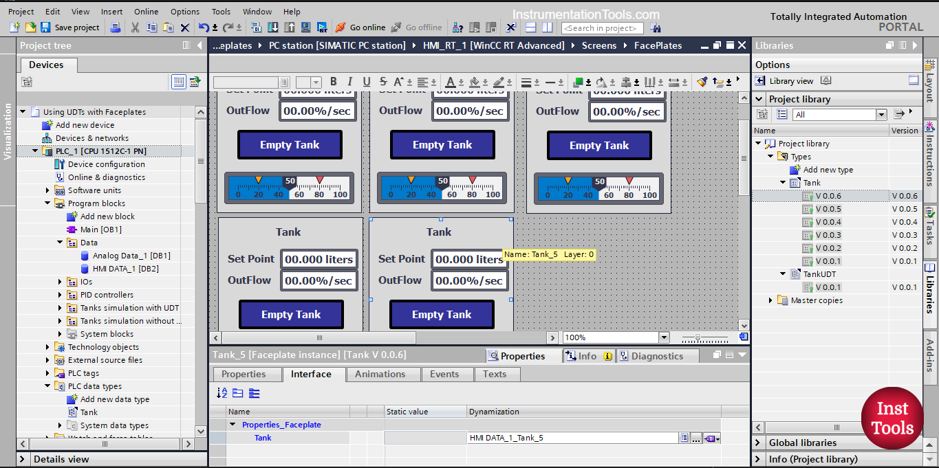
Now that we implemented the UDT within our faceplate, any faceplate instance will have only one interface that we need to connect to our PLC. See picture 16.
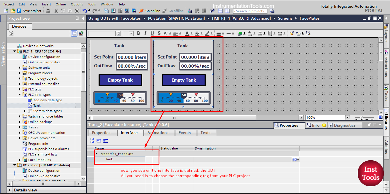
picture 16. Any faceplate instance has only one interface tag.
For tank 1 visualization, we will connect the faceplate instance 1 to the UDT Tank_1. See picture 17.
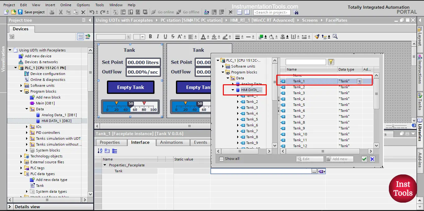
picture 17. Tank _1 faceplate instance.
The whole connection between your visualization and your PLC is now done with one tag in one step. See picture 18.
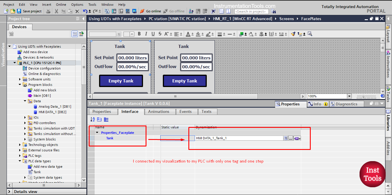
picture 18. Connection between faceplate and PLC with 1 tag.
Now, I can add as many faceplate instances as I want and it will be just as easily. See picture 19.
Picture 19. Adding multiple faceplate instances.
Edit the UDT in the global library
You should know that any change you need to make to your UDT will be considered as a new version in work, as now your UDT has become a global type and not just defined for the PLC project.
To do so, you just right-click on your UDT type and press edit type. see picture 20.
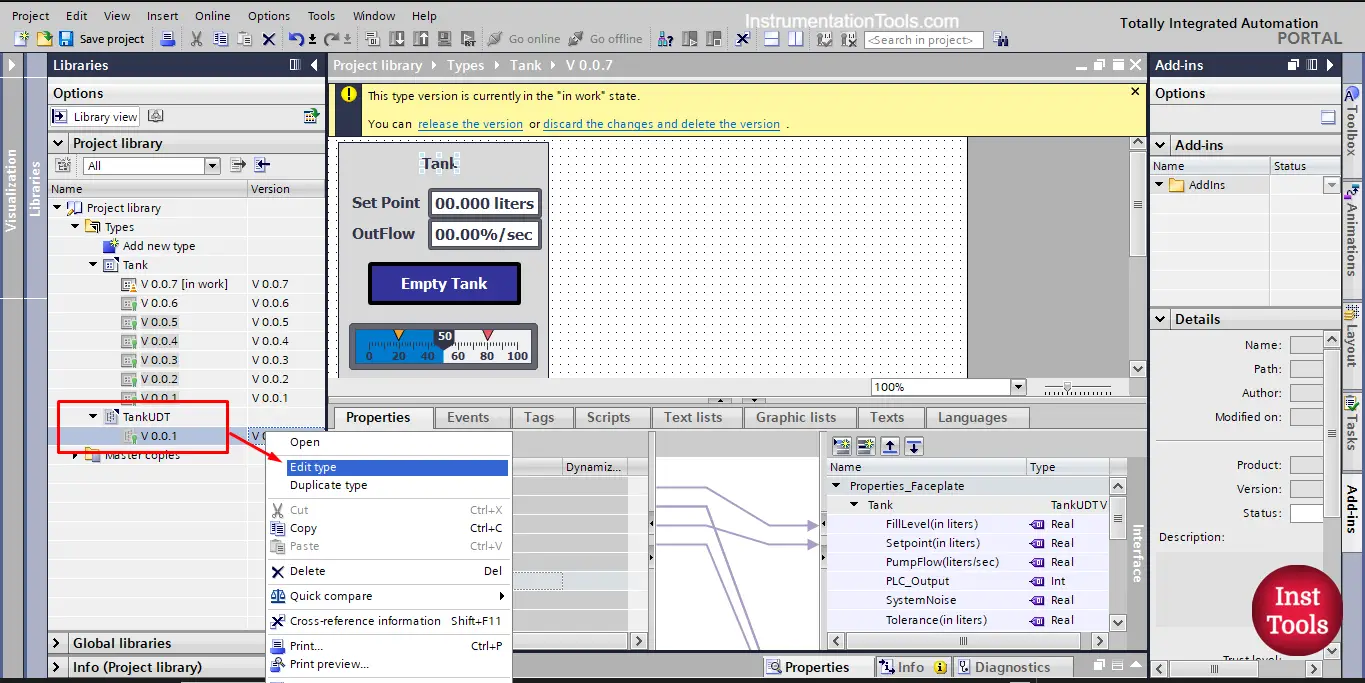
picture 20. Edit the UDT type.
After you press edit type, a new version in the work of the UDT will open, and you can add or delete internal tags.
Once you finish your editing you will need to release the type version to apply the changes you made. See picture 21.
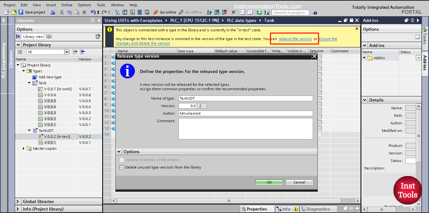
picture 21. Release the UDT new version.
You will need to reselect the UDT version in your faceplate properties to have the new changes applied to your faceplate property. See picture 22.
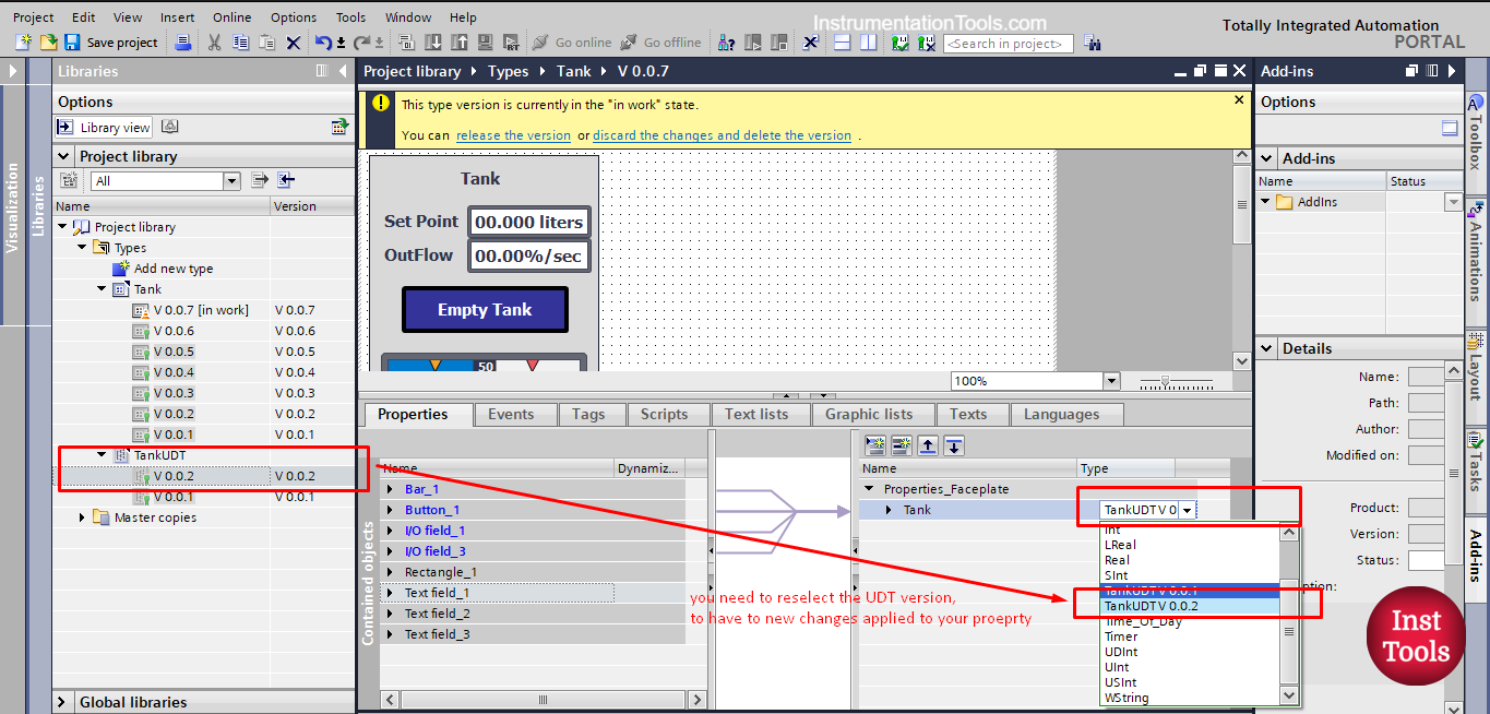
Picture 22. Reselect the UDT type.
Download: Faceplate with UDT
Conclusion
- Using UDTs with faceplates will make it even easier and faster to create visualization for your PLC project.
- To be able to use UDTs with faceplates, we have to define the UDT globally in our project.
- Any changes made to the faceplate or the UDT type will require editing and releasing a new version of that type.
If you liked this article, then please subscribe to our YouTube Channel for Instrumentation, Electrical, PLC, and SCADA video tutorials.
You can also follow us on Facebook and Twitter to receive daily updates.
Read Next:
- PLC PID Controller Output Types
- Static and Temp Variables in PLC
- Power Supply Sizing for Systems
- How to Read the PLC Datasheet?
- Update the Firmware Version of PLC