A Safety Instrumented Function, or SIF, is one or more components designed to execute a specific safety-related task in the event of a specific dangerous condition.
The over-temperature shutdown switch inside a clothes dryer or an electric water heater is a simple, domestic example of an SIF, shutting off the source of energy to the appliance in the event of a detected over-temperature condition.
Safety Instrumented Functions are alternatively referred to as Instrument Protective Functions, or IPFs.
A Safety Instrumented System, or SIS, is a collection of SIFs designed to bring an industrial process to a safe condition in the event of any dangerous detected conditions.
Also known as Emergency Shutdown (ESD) or Protective Instrument Systems (PIS), these systems serve as an additional “layer” of protection against process equipment damage, adverse environmental impact, and/or human injury beyond the protection normally offered by a properly operating regulatory control system.
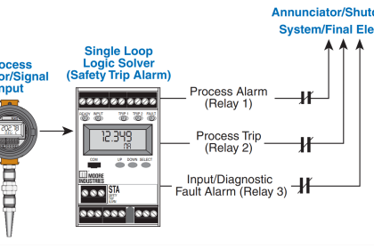
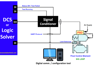
Like all automatic control systems, an SIS consists of three basic sections:
- Sensor(s) to detect a dangerous condition,
- Controller to decide when to shut down the process, and
- Final control element(s) to actually perform the shutdown action necessary to bring the process to a safe condition.
Sensors may consist of process switches and/or transmitters separate from the regulatory control system.
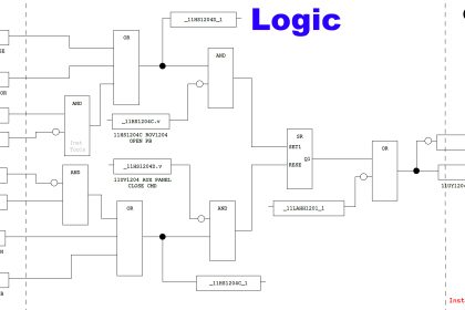
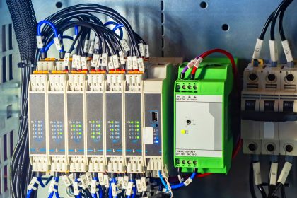
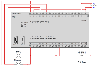
Controller for an SIS is usually called a logic solver, and is also separate from the regular control system.
Final control elements for an SIS may be special on/off valves (often called “chopper” valves) or override solenoids used to force the normal control valve into a shutdown state.
Some industries, such as chemical processing and nuclear power, have extensively employed safety instrumented systems for many decades.
Likewise, automatic shutdown controls have been standard on steam boilers and combustion furnaces for years. The increasing capability of modern instrumentation, coupled with the realization of enormous costs (both social and fiscal) resulting from industrial disasters has pushed safety instrumentation to new levels of sophistication and new breadths of application. It is the purpose of this section to explore some common safety instrumented system concepts as well as some specific industrial applications.
One of the challenges inherent to safety instrumented system design is to balance the goal of maximum safety against the goal of maximum economy. If an industrial manufacturing facility is equipped with enough sensors and layered safety shutdown systems to virtually ensure no unsafe condition will ever prevail, that same facility will be plagued by “false alarm” and “spurious trip” events (Note 1) where the safety systems malfunction in a manner detrimental to the profitable operation of the facility. In other words, a process system designed with an emphasis on automatic shut-down will probably shut down more frequently than it actually needs to.
While the avoidance of unsafe process conditions is obviously a noble goal, it cannot come at the expense of economically practical operation or else there will be no reason for the facility to exist at all (Note 2).
A safety system must fulfill its intended protective function, but not at the expense of compromising the intended purpose of the facility.
Note 1 : Many synonyms exist to describe the action of a safety system needlessly shutting down a process. The term “nuisance trip” is often (aptly) used to describe such events. Another (more charitable) label is “fail-to-safe,” meaning the failure brings the process to a safe condition, as opposed to a dangerous condition.
Note 2: Of course, there do exist industrial facilities operating at a financial loss for the greater public benefit (e.g. certain waste processing operations), but these are the exception rather than the rule. It is obviously the point of a business to turn a profit, and so the vast majority of industries simply cannot sustain a philosophy of safety at any cost. One could argue that a “paranoid” safety system even at a waste processing plant is unsustainable, because too many “false trips” result in inefficient processing of the waste, posing a greater public health threat the longer it remains unprocessed.
This tension is understood well within the electric power generation and distribution industries. Faults in high-voltage electrical lines can be very dangerous, as well as destructive to electrical equipment.
For this reason, special protective devices are placed within power systems to monitor conditions and halt the flow of electricity if those conditions become threatening.
However, the very presence of these devices means it is possible for power to accidently shut off, causing unnecessary power outages for customers. In the electrical industry, the word “dependability” refers to the probability that the protective systems will cut power when required.
By contrast, the word “security” is used in the electrical industry to refer to the avoidance of unnecessary outages. We will apply these terms to general process systems.
To illustrate the tension between dependability and security in a fluid process system, we may analyze a double-block shutoff valve (Note 3) system for a petroleum pipeline:
Note 3: As drawn, these valves happen to be ball-design, the first actuated by an electric motor and the second actuated by a pneumatic piston.
As is often the case with redundant instruments, an effort is made to diversify the technology applied to the redundant elements in order to minimize the probability of common-cause failures.
If both block valves were electrically actuated, a failure of the electric power supply would disable both valves. If both block valves were pneumatically actuated, a failure of the compressed air supply would disable both valves.
The use of one electric valve and one pneumatic valve grants greater independence of operation to the double-block valve system.
The safety function of these block valves is, of course, to shut off flow from the petroleum source to the distribution pipeline in the event that the pipeline suffers a leak or rupture.
Having two block valves in “series” adds an additional layer of safety, in that only one of the block valves need shut to fulfill the safety (dependability) function. Note the use of two different valve actuator technologies: one electric (motor) and the other a piston (either pneumatic or hydraulically actuated).
This diversity of actuator technologies helps avoid common-cause failures, helping to ensure both valves will not simultaneously fail due to a single cause.
However, the typical operation of the pipeline demands both block valves be open in order for petroleum to flow through it. The presence of redundant (dual) block valves, while increasing safety, decreases security for the pipeline.
If either of the two block valves happened to fail shut when there was no need to shut off the pipeline, flow through the pipeline would needlessly halt.
Having two series-plumbed block valves instead of one block valve increases the probability of unnecessary pipeline shutdowns.
A precise notation useful for specifying dependability and security in redundant systems compares the number of redundant elements necessary to achieve the desired result compared to the total number of redundant elements.
If the desired result for our double-block valve array is to shut down the pipeline in the event of a detected leak or rupture, we would say the system is one out of two (1oo2) redundant for dependability.
In other words, only one out of the two redundant valves needs to function properly (shut off) in order to bring the pipeline to a safe condition. If the desired result is to allow flow through the pipeline when the pipeline is leak-free, we would say the system is two out of two (2oo2) redundant for security.
This means both of the two block valves need to function properly (open up) in order to allow petroleum to flow through the pipeline.
This numerical notation showing the number of essential elements versus number of total elements is often referred to as MooN (“M out of N”) notation, or sometimes as NooM (“N out of M”) notation (Note 4). When discussing safety instrumented systems, the ISA standard 84 defines redundancy in terms of the number of agreeing channels necessary to perform the safety (shutdown) function – in other words, the ISA’s usage of “MooN” notation implies dependability, rather than security.
Note 4 : For what it’s worth, the ISA safety standard 84 defines this notation as “MooN,” but I have seen sufficient examples of the contrary (“NooM”) to question the authority of either label.
A complementary method of quantifying dependability and security for redundant systems is to label in terms of how many element failures the system may sustain while still achieving the desired result.
For this series set of double block valves, the safety (shutdown) function has a fault tolerance of one (1), since one of the valves may fail to shut when called upon but the other valve remains sufficient in itself to shut off the flow of petroleum to the pipeline.
The normal operation of the system, however, has a fault tolerance of zero (0). Both block valves must open up when called upon in order to establish flow through the pipeline.
It should be clearly evident that a series set of block valves emphasizes dependability (the ability to shut off flow through the pipeline when needed) at the expense of security (the ability to allow normal flow through the pipeline when there is no leak).
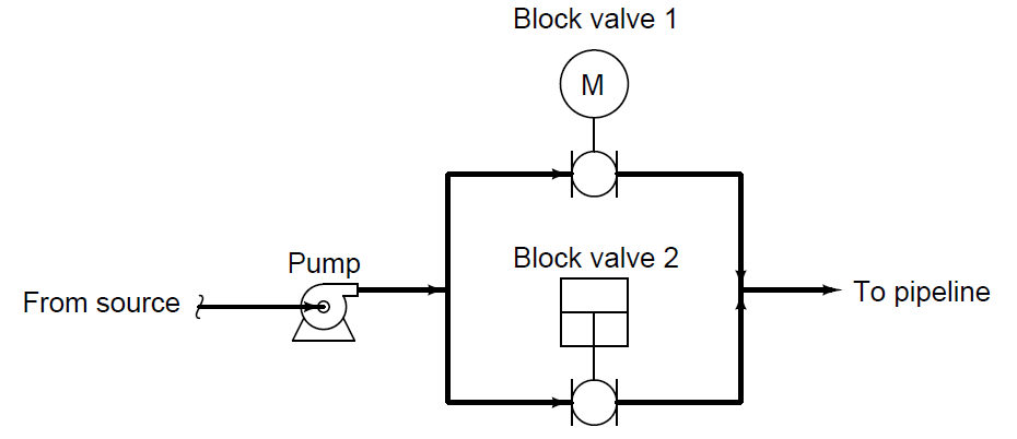
We may now analyze a parallel block valve scheme to compare its redundant characteristics:
In this system, the safety (dependability) redundancy function is 2oo2, since both block valves would have to shut off in order to bring the pipeline to a safe condition in the event of a detected pipeline leak.
However, security would be 1oo2, since only one of the two valves would have to open up in order to establish flow through the pipeline.
Thus, a parallel block valve array emphasizes production (the ability to allow flow through the pipeline) over safety (the ability to shut off flow through the pipeline).
Another way to express the redundant behavior of the parallel block valve array is to say that the safety function has a fault tolerance of zero (0), while the production function has a fault tolerance of one (1).
One way to avoid compromises between dependability and security is to increase the number of redundant components, forming arrays of greater complexity.
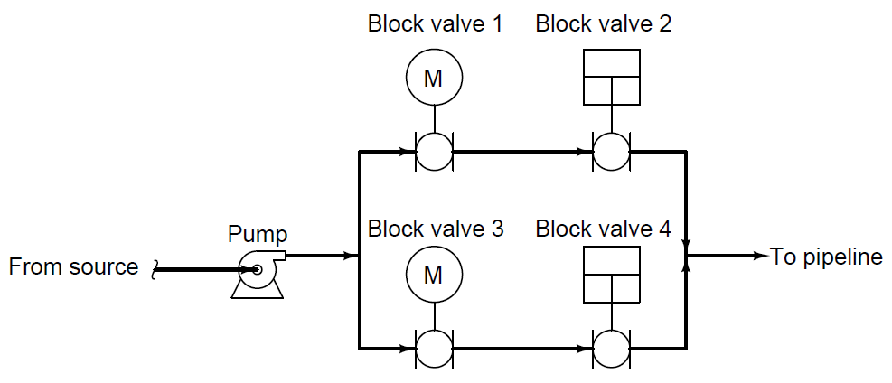
Consider this quadruple block valve array, designed to serve the same function on a petroleum pipeline:
In order to fulfill its safety function of shutting off the flow of petroleum to the pipeline, both parallel pipe “branches” must be shut off.
At first, this might seem to indicate a two-out-of-four (2oo4) dependability, because all we would need is for one valve in each branch (two valves total) out of the four valves to shut off in order to shut off flow to the pipeline.
We must remember, however, that we do not have the luxury of assuming idealized faults. If only two of the four valves function properly in shutting off, they just might happen to be two valves in the same branch, in which case two valves properly functioning is not enough to guarantee a safe pipeline condition.
Thus, this redundant system actually exhibits three-out-of-four (3oo4) dependability (i.e. it has a safety fault tolerance of one), because we need three out of the four block valves to properly shut off in order to guarantee a safe pipeline condition.
Analyzing this quadruple block valve array for security, we see that three out of the four valves need to function properly (open up) in order to guarantee flow to the pipeline.
Once again, it may appear at first as though all we need are two of the four valves to open up in order to establish flow to the pipeline, but this will not be enough if those two valves happen to be in different parallel branches.
So, this system exhibits three-out-of-four (3oo4) security (i.e. it has an production fault tolerance of one).

