Inst ToolsInst ToolsInst Tools
  • Courses
  • Automation
    • PLC
    • Control System
    • Safety System
    • Communication
    • Fire & Gas System
  • Instrumentation
    • Design
    • Pressure
    • Temperature
    • Flow
    • Level
    • Vibration
    • Analyzer
    • Control Valve
    • Switch
    • Calibration
    • Erection & Commissioning
  • Interview
    • Instrumentation
    • Electrical
    • Electronics
    • Practical
  • Q&A
    • Instrumentation
    • Control System
    • Electrical
    • Electronics
    • Analog Electronics
    • Digital Electronics
    • Power Electronics
    • Microprocessor
  • Request
Search
  • Books
  • Software
  • Projects
  • Process
  • Tools
  • Basics
  • Formula
  • Power Plant
  • Root Cause Analysis
  • Electrical Basics
  • Animation
  • Standards
  • 4-20 mA Course
  • Siemens PLC Course
Reading: Procedure for Crimping the Connector
Share
Notification Show More
Font ResizerAa
Inst ToolsInst Tools
Font ResizerAa
  • Courses
  • Design
  • PLC
  • Interview
  • Control System
Search
  • Courses
  • Automation
    • PLC
    • Control System
    • Safety System
    • Communication
    • Fire & Gas System
  • Instrumentation
    • Design
    • Pressure
    • Temperature
    • Flow
    • Level
    • Vibration
    • Analyzer
    • Control Valve
    • Switch
    • Calibration
    • Erection & Commissioning
  • Interview
    • Instrumentation
    • Electrical
    • Electronics
    • Practical
  • Q&A
    • Instrumentation
    • Control System
    • Electrical
    • Electronics
    • Analog Electronics
    • Digital Electronics
    • Power Electronics
    • Microprocessor
  • Request
Follow US
All rights reserved. Reproduction in whole or in part without written permission is prohibited.
Inst Tools > Blog > Common > Procedure for Crimping the Connector

Procedure for Crimping the Connector

Last updated: December 31, 2017 8:19 am
Editorial Staff
Common
No Comments
Share
3 Min Read
SHARE

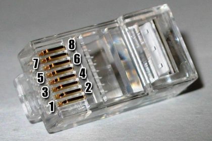
Procedure for crimping the connector:

For tubing we used double compression type fitting. Following are the procedure for the tubing:

  1. First select the proper size tube (Like as 6 mm, 10 mm, 12 mm OD). Tube size may depend on your pressure and process services. Material of tube also plays a major role so material also should choose as per your requirement.

Note: There is small difference in inches and mm tubing so choose the correct fitting.

As ¼ “tube and 6 mm tube looks like same.

  1. Inspect the tube. In inspection following point to consider
  2. Check no bending has been occurred. If bending is present in tube then its restrict the flow.
  3. Check the tube path has been cleared. Tube may flush with instrument air to ensure that there is no chocking.
  4. If scratching also present on tube then tubing will not fit the I.D. of the ferrule(s) or the body bore properly and will cause leakage
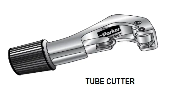
  5. Cutting the tube at the end with tube cutter. Tube can be cut with hexa but it’s should cut the straight most probably refer the tube cutter.

Cutting with Tube cutter: Tube cutter commonly used to cut the tube insert the tube between blade and guider and then move the tuber cutter clockwise and tighten the tube after one cycle then again move cutter one cycle. This is done till the tube cute.

Tube cutter

Cutting with a Hacksaw: – When using a hacksaw to cut off tubing, use a guide to hold the tube to assure the square cut off.

  1. De burring the tube: After the cutting the tube burs are formed which damaging the system. OD burrs can prevent tubing for proper sealing in a connector. ID burs restrict the flow of process. So deburring is removed by flat and round file.
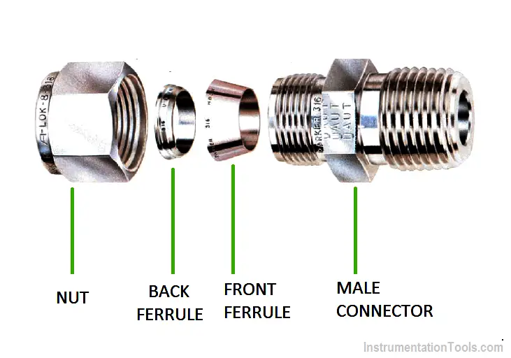
  2. Assembly the Connector: Ferule and connector should be sequenced as shown in figure. If direction is differing then it’s not compress and not fitted proper. Arrange in sequence then tighten the nut on male connector with both ferrules by hand.

Tube Fitting Parts

Insert the tube in connector and insure that the tube properly fixed in male connector then tight the nut with hand then it’s tightening with slide wrench. Hold the male connector with other wrench and tighten this.

Instrument Tube Installation

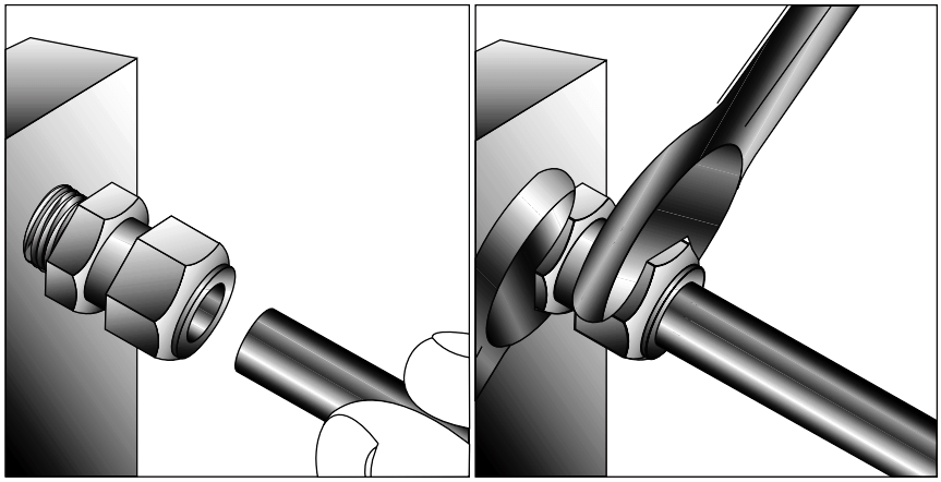
Loosen the nut then checked both ferrule are compressed and no loosen.

Instrument Tube Ferrule

Image Credits :  Parker instrument and fittings

Article by :
Ashish Agrawal
Don't Miss Our Updates
Be the first to get exclusive content straight to your email.
We promise not to spam you. You can unsubscribe at any time.
Invalid email address
You've successfully subscribed !

Continue Reading

Capacity Control of Absorption Chillers
Vacuum Technology is Enabling New Era of Ultra-Powerful Computers: Quantum Computing
Essential Safety Tips for Glass Workers
IoT Engineer Job Roles and Responsibilities
Top US Universities that Offer Online Education
How to Protect Electrical Terminal Blocks From Tampering?
Share This Article
Facebook Whatsapp Whatsapp LinkedIn Copy Link
Share
Leave a Comment

Leave a Reply Cancel reply

Your email address will not be published. Required fields are marked *

Stay Connected

128.3kFollowersLike
69.1kFollowersFollow
210kSubscribersSubscribe
38kFollowersFollow

Categories

Explore More

Electrification in Mining Industry
HVAC Valves
Wet Dust Suppression System
Proximity Sensor
Importance of Device Diagnostics
Multiple Lags (orders)
Difference Between NPT, BSPP and BSPT Seals
Why is Capacitor Used in a Fan?

Keep Learning

Confined Space

9 Life-Saving Rules for Oil and Gas Industry

Types of Equipment Needed to Run a Successful Auto Repair Shop

Types of Equipment Needed to Run a Successful Auto Repair Shop

Sugar Plant - Automatic Control of Massecuite Feed

Sugar Plant – Automatic Control of Massecuite Feed

Difference Between Robotics and Automation

Difference Between Robotics and Automation

What Do You Learn in Software Engineering

What Do You Learn in Software Engineering?

Top Most Popular CNC Software Programs

Top Most Popular CNC Software Programs – A Comprehensive List

FPGA vs. CPLD - What are the differences between them

FPGA vs. CPLD – What are the differences between them

Shaper Machine Hydraulic Circuit Design

Hydraulic Shaper Machine – Components, Circuit, Principle

Learn More

Electricity and Magnetism Questions & Answers

Top 300 Electricity and Magnetism Questions & Answers

Instrument Technicians Tools - Instrumentation MCQ Questions

Instrument Technicians Tools – Instrumentation Test

Swiss Screw Machining

Things You Should Know About Swiss Screw Machining

Programmable Logic Controller (PLC) Questions and Answers

Programmable Logic Controller (PLC) Questions and Answers – 6

Formula of AMP, KW, KVA, HP for AC and DC Voltages

Formula of AMP, KW, KVA, HP for AC and DC Voltages

reverse-biased varactor diode

Varactor Diode Operation

thermocouple voltages

Manually Interpreting Thermocouple Voltages

PLC Program for Solenoid, Pilot Lamp, and Switch with Alarm

PLC Program for Solenoid, Pilot Lamp, and Switch with Alarm

Menu

  • About
  • Privacy Policy
  • Copyright

Quick Links

  • Learn PLC
  • Helping Hand
  • Part Time Job

YouTube Subscribe

Follow US
All rights reserved. Reproduction in whole or in part without written permission is prohibited.
Welcome Back!

Sign in to your account

Username or Email Address
Password

Lost your password?