Inst ToolsInst ToolsInst Tools
  • Courses
  • Automation
    • PLC
    • Control System
    • Safety System
    • Communication
    • Fire & Gas System
  • Instrumentation
    • Design
    • Pressure
    • Temperature
    • Flow
    • Level
    • Vibration
    • Analyzer
    • Control Valve
    • Switch
    • Calibration
    • Erection & Commissioning
  • Interview
    • Instrumentation
    • Electrical
    • Electronics
    • Practical
  • Q&A
    • Instrumentation
    • Control System
    • Electrical
    • Electronics
    • Analog Electronics
    • Digital Electronics
    • Power Electronics
    • Microprocessor
  • Request
Search
  • Books
  • Software
  • Projects
  • Process
  • Tools
  • Basics
  • Formula
  • Power Plant
  • Root Cause Analysis
  • Electrical Basics
  • Animation
  • Standards
  • 4-20 mA Course
  • Siemens PLC Course
Reading: Troubleshooting a Biased Transistor
Share
Font ResizerAa
Inst ToolsInst Tools
Font ResizerAa
  • Courses
  • Design
  • PLC
  • Interview
  • Control System
Search
  • Courses
  • Automation
    • PLC
    • Control System
    • Safety System
    • Communication
    • Fire & Gas System
  • Instrumentation
    • Design
    • Pressure
    • Temperature
    • Flow
    • Level
    • Vibration
    • Analyzer
    • Control Valve
    • Switch
    • Calibration
    • Erection & Commissioning
  • Interview
    • Instrumentation
    • Electrical
    • Electronics
    • Practical
  • Q&A
    • Instrumentation
    • Control System
    • Electrical
    • Electronics
    • Analog Electronics
    • Digital Electronics
    • Power Electronics
    • Microprocessor
  • Request
Follow US
All rights reserved. Reproduction in whole or in part without written permission is prohibited.
Inst Tools > Blog > Electronic Devices & Circuits > Troubleshooting a Biased Transistor

Troubleshooting a Biased Transistor

Last updated: September 27, 2016 7:49 am
Editorial Staff
Electronic Devices & Circuits
No Comments
Share
1 Min Read
SHARE

Several faults can occur in a simple transistor bias circuit. Possible faults are open bias resistors, open or resistive connections, shorted connections, and opens or shorts internal to the transistor itself. The above Figure is a basic transistor bias circuit with all voltages referenced to ground.
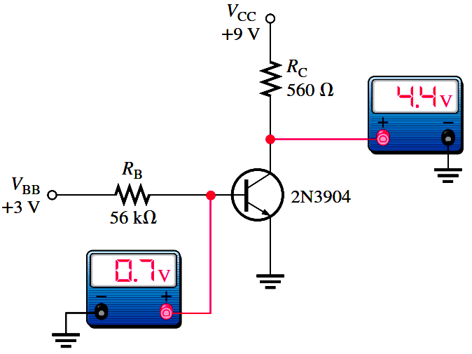
Troubleshooting a Biased Transistor

The two bias voltages are VBB = 3 V and VCC = 9 V. The correct voltage measurements at the base and collector are shown. Analytically, these voltages are verified as follows. A bDC = 200 is taken as midway between the minimum and maximum values of hFE given on the datasheet for the 2N3904 (Note : Download transistor datasheet for reference). A different hFE (bDC), of course, will produce different results for the given circuit.

transistor-troubleshooting.png


Don't Miss Our Updates
Be the first to get exclusive content straight to your email.
We promise not to spam you. You can unsubscribe at any time.
Invalid email address
You've successfully subscribed !

Continue Reading

Ripple Voltage in Rectifiers
Transistor Voltage Divider Bias
Difference between ideal diode & conventional diode
Bipolar Junction Transistor Construction
Cathode Ray Tube Deflection System
Cathode Ray Tube (CRT)
Share This Article
Facebook Whatsapp Whatsapp LinkedIn Copy Link
Share
Leave a Comment

Leave a Reply Cancel reply

Your email address will not be published. Required fields are marked *

Stay Connected

128.3kFollowersLike
69.1kFollowersFollow
210kSubscribersSubscribe
38kFollowersFollow

Categories

Explore More

Freewheeling Diode Working Principle
What is a Filter Circuit ?
Current Divider Rule
Electron Gun of Cathode Ray Tube
pi filter Operation
Zener Diode Voltage Regulator Operation
Summary Of Transistor Bias Circuits
Short Notes on Rectifiers & Filters

Keep Learning

Transistor as an Amplifier in Common Emitter

Transistor as an Amplifier in Common Emitter

Power MOSFET Safe Operating Area

Power MOSFET Safe Operating Area

diode-limiter-principle

Diode Limiters/Clippers Operation

schottky diode working principle

Schottky Diode Working Principle

MOSFET VI Characteristics

Power MOSFET

Center Tapped Full Wave Rectifier Operation

Center Tapped Full Wave Rectifier Operation

phototransistor-circuit

Phototransistor Circuit Example

full-wave-bridge-rectifier-with-voltage-regulator

Basics of Voltage Regulators

Learn More

What is Open Telemetry?

What is Open Telemetry? – Principles and Benefits

Diodes Voltage Tripler

Diodes Voltage Tripler

Mechanical Vibration Switch

Vibration Switch Working Principle

Fire Extinguishers Mock Test

Fire Extinguishers Mock Test

Comparison of Flowmeters

Difference between Different Types of Flow Meters

Tagging Philosophy for Junction Box

Tagging Philosophy for Junction Box, Cable, and Cable Drum

Choked Flow of Control Valve

Choked Flow of Control Valves

Example PLC Program to Control a Pump based on Level Sensors

Example PLC Program to Control a Pump based on Level Sensors

Menu

  • About
  • Privacy Policy
  • Copyright

Quick Links

  • Learn PLC
  • Helping Hand
  • Part Time Job

YouTube Subscribe

Follow US
All rights reserved. Reproduction in whole or in part without written permission is prohibited.
Welcome Back!

Sign in to your account

Username or Email Address
Password

Lost your password?