Inst ToolsInst ToolsInst Tools
  • Courses
  • Automation
    • PLC
    • Control System
    • Safety System
    • Communication
    • Fire & Gas System
  • Instrumentation
    • Design
    • Pressure
    • Temperature
    • Flow
    • Level
    • Vibration
    • Analyzer
    • Control Valve
    • Switch
    • Calibration
    • Erection & Commissioning
  • Interview
    • Instrumentation
    • Electrical
    • Electronics
    • Practical
  • Q&A
    • Instrumentation
    • Control System
    • Electrical
    • Electronics
    • Analog Electronics
    • Digital Electronics
    • Power Electronics
    • Microprocessor
  • Request
Search
  • Books
  • Software
  • Projects
  • Process
  • Tools
  • Basics
  • Formula
  • Power Plant
  • Root Cause Analysis
  • Electrical Basics
  • Animation
  • Standards
  • 4-20 mA Course
  • Siemens PLC Course
Reading: Difference Between Trunking and Conduit
Share
Notification Show More
Font ResizerAa
Inst ToolsInst Tools
Font ResizerAa
  • Courses
  • Design
  • PLC
  • Interview
  • Control System
Search
  • Courses
  • Automation
    • PLC
    • Control System
    • Safety System
    • Communication
    • Fire & Gas System
  • Instrumentation
    • Design
    • Pressure
    • Temperature
    • Flow
    • Level
    • Vibration
    • Analyzer
    • Control Valve
    • Switch
    • Calibration
    • Erection & Commissioning
  • Interview
    • Instrumentation
    • Electrical
    • Electronics
    • Practical
  • Q&A
    • Instrumentation
    • Control System
    • Electrical
    • Electronics
    • Analog Electronics
    • Digital Electronics
    • Power Electronics
    • Microprocessor
  • Request
Follow US
All rights reserved. Reproduction in whole or in part without written permission is prohibited.
Inst Tools > Blog > Electrical Basics > Difference Between Trunking and Conduit

Difference Between Trunking and Conduit

In Trunking, the cables are covered in a rectangular cabinet. In a conduit system, the cables are fully covered inside a closed cabinet.

Last updated: January 23, 2024 2:14 pm
Viral Nagda
Electrical Basics
1 Comment
Share
5 Min Read
SHARE

Whenever you use cables in any application, it is necessary that it is protected and routed properly in the required direction. Any improper exposure of cables or wrong direction of wiring can damage the cables.

Contents
What is Trunking?What is Conduit?Difference Between Trunking and Conduit

So, there are many methods through which electrical and instrument cables are routed and covered in a proper manner for use. Two of the most used ones are – conduit and trunking. They are used in almost all the systems of cable applications. In this post, we will see the difference between conduit and trunking.

What is Trunking?

Trunking is a method by which the cables are covered in a rectangular cabinet, whose cover is removable. This allows the engineers to maintain the cables whenever required easily, as the cover is removable.

Refer to the below image for understanding. As you can see, the left-hand side of the long rectangular cabinet houses the cables and is covered by a bracket which can be removed anytime for troubleshooting and maintenance.

What is Trunking
Image Courtesy: Wikimedia

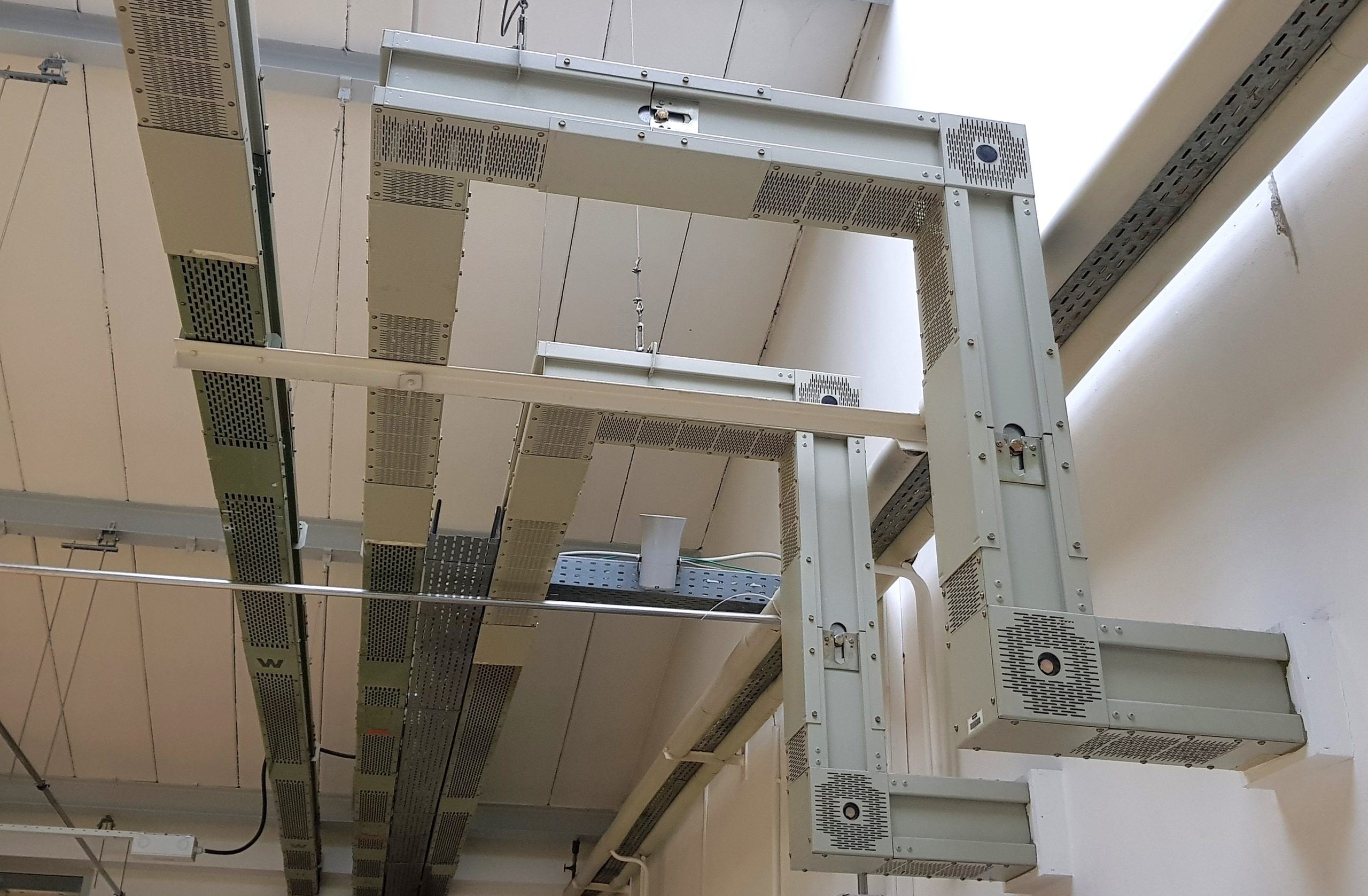
Basically, trunking is best used in systems where frequent maintenance is required and where installation will require constant changes. All the cables are bundled together, routed properly through a trunk, and then distributed wherever required.

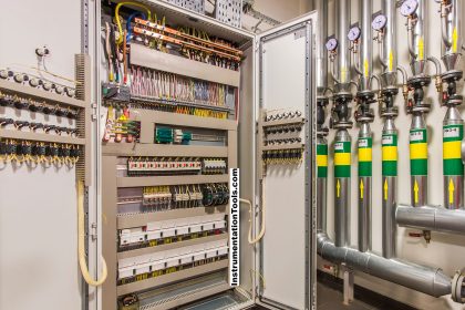
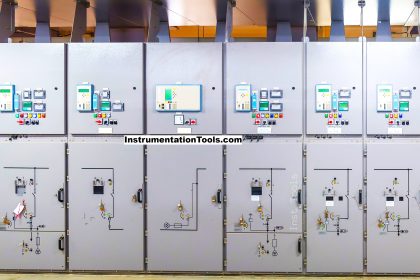
The best and simplest example of a trunk system is an electrical PLC panel. You must have seen how the cables inside the panel are routed through a removable bracket trunk, which makes wiring and maintenance easy. Its main focus is thus, to keep multiple cables tidy and easily accessible.

What is Conduit?

A conduit system on the other hand is a type of cable enclosure, where the cables are fully covered inside a closed cabinet and not easily accessible. It is similar to a metal pipe.

The cables are routed and arranged inside a piping-type cabinet, bundled together, and distributed wherever required. Its main job is to fully protect the cables from damage and allow very little access for maintenance.

It means the cables must be installed properly in one go and if any maintenance activity comes, then the user must be prepared for a long downtime period. Refer to the below image for understanding.

Electrical Conduit
Image Courtesy: Wikimedia

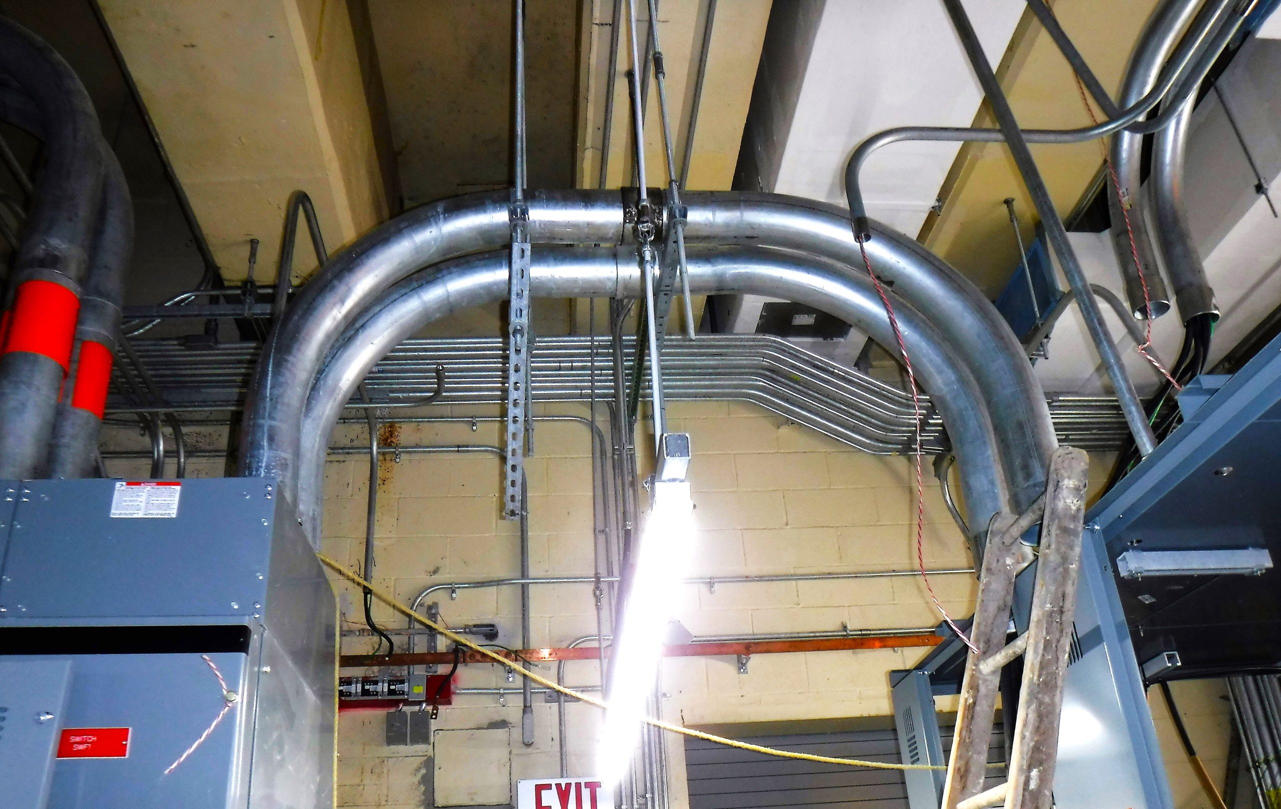
As you can see, a circular pipe section runs in the system, which houses the cables and then carries them wherever required. Conduit is typically made of rigid or flexible metal, PVC, or other durable materials that ensure the protection of the wires inside from external damage.

Difference Between Trunking and Conduit

The main differences between trunking and conduit are mentioned below.

  1. As discussed earlier, a trunking system allows cabinet frames to be removed and re-install the cables whenever required easily; whereas a conduit system does not allow the cabinet frames to be removed frequently as they are fixed in position.
  2. Types of trunking systems are – cable, bus bar, lighting, and multi-compartment. Types of conduit systems are – steel, PVC, and stainless steel.
  3. The reliability and durability of a conduit system are higher than a trunking system.
  4. The conduit system is ideal for installations in external and damp environments, and hazardous environments. A trunking system is ideal for the distribution of cables in buildings, equipment, and switching yards.
  5. As trunking is designed for easy accessibility and maintenance, they are not visually appalling. They look messy and cumbersome if not installed properly. Conduit systems on the other hand look visually appalling, as their primary task is to protect cables by fixed enclosures.

In this way, we saw the difference between trunking and conduit cable systems.

If you found this article informative and engaging, we encourage you to consider subscribing to our YouTube Channel, where you can access video tutorials covering topics such as Instrumentation, Electrical, PLC, and SCADA.

For daily updates and to stay connected with our latest content, be sure to follow us on Facebook and Twitter.

To further expand your knowledge, we recommend checking out our next insightful articles.

Read Next:

  • Single Core and Multi-Core Cables
  • Difference Between HV and LV Cables
  • Types of Cables in Industrial Automation
  • Instrumentation Cables Testing Steps
  • Flame Resistant and Retardant Cables
Don't Miss Our Updates
Be the first to get exclusive content straight to your email.
We promise not to spam you. You can unsubscribe at any time.
Invalid email address
You've successfully subscribed !

Continue Reading

What is a Current Transformer?
What is a Motor Disconnector Switch? – Purpose, Principle, Factors
Root Cause Analysis – Burst Transformers and 11 kV Input Breakers
How to Protect Electrical Terminal Blocks From Tampering?
One Nation One Grid One Frequency – Electrical Engineering
What is a Protective Relay? Principle, Advantages, Applications
Share This Article
Facebook Whatsapp Whatsapp LinkedIn Copy Link
Share
1 Comment
  • Louetri Rabie says:
    November 21, 2023 at 11:51 pm

    Thinke you vers mutch

    Reply

Leave a Reply Cancel reply

Your email address will not be published. Required fields are marked *

Stay Connected

128.3kFollowersLike
69.1kFollowersFollow
210kSubscribersSubscribe
38kFollowersFollow

Categories

Explore More

What is a Submersible Pump? Principle Advantages Disadvantages
What are Ground Fault and Earth Fault?
What is Floating Neutral? – Electrical Engineering Basics
Difference between RCCB and RCBO
What are Switchgear Interlocks?
Types of Motor Enclosures
Effects of Long Distance Cables between VFD and Motor
Difference between Power Cables and Signal Cables

Keep Learning

Electrical Maintenance Engineer's Biggest Enemy

Electrical Components Overheating – Causes, Troubles, Prevent

Current Transformer Operation

Current Transformer Selection, Operation & Maintenance

Variable Frequency Drive - Converter

Variable Frequency Drive (VFD) Working Principle

Stepper Motor Working Principle Animation

Stepper Motor Working Principle

Why is IGBT used in VFD

Why is IGBT used in VFD?

4-20mA VFD Drive Formula

4-20mA Linear Conversion Calculation for VFD Drive (Formula)

Star and Delta Wiring Animation

Basics of Star and Delta connections

MCB vs Fuse

MCB vs Fuse Questions and Answers

Learn More

ATEX Standards

ATEX Standards

Instruments Troubleshooting - Problems, Causes, Corrective Actions

Instruments Troubleshooting – Problems, Causes, Corrective Actions

Instrument Heat Trace

Electrical Heat Tracing

Oval gear Flow Meter Principle

Oval Gear Meter – Principle, Advantages, Limitations, Applications

Two Wattmeters to Measure 3 Phase Power

Three Phase Wattmeter

Power Supply Unit with Diode Protection

Why we use Diode Protection Modules ?

Level Transmitter

What is a Bridle?

current-limiting-reactors-and-short-circuit-currents

Current Limiting Reactors and Short Circuit Currents

Menu

  • About
  • Privacy Policy
  • Copyright

Quick Links

  • Learn PLC
  • Helping Hand
  • Part Time Job

YouTube Subscribe

Follow US
All rights reserved. Reproduction in whole or in part without written permission is prohibited.
Welcome Back!

Sign in to your account

Username or Email Address
Password

Lost your password?