Types of Contact Vibration Measurement
Path Measurement
- Potentiometer Type
- LVDT Type
Speed Measurement
- Electrodynamics
- Seismometer
Acceleration measurement
- Piezoelectric sensor
- Piezo-resistive sensor
- Resistive sensor
- Inductive sensor
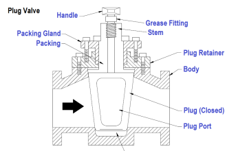
Path Measurement
Potentiometric Transmitter
The potentiometric transmitter is a one-dimensional position sensor. It is based on the potentiometer, an adjustable potential divider. A voltage is applied to a resistive track. A wiper runs along this resistive track and thus divides the resistor in two parts, as shown in figure (resistor R1 and R2).
At different positions of the wiper, specific resulting voltages can be measured, due to the change in resistance. The wiper moves because it is attached to the motion of the vibrating object. The frequency ranges from 5 Hz to 2 kHz, which corresponds to a possible maximum acceleration of 20 g. Potentiometric transmitters can achieve measuring strokes from 1 mm up to 2 m with an infinite resolution. The operating temperature ranges between double-digit temperatures below zero and 150 °C
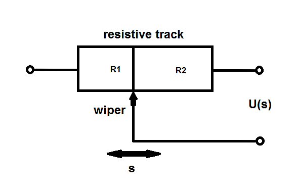
figure 1: Potentiometric transmitter (schematic)
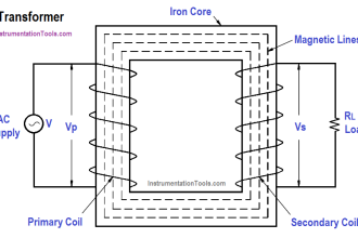
Linear Variable Differential Transformer
The Linear Variable Differential Transformer (LVDT) is a kind of transformer which is based on induction. It can be used for relative measurement of the displacement. As shown in figure 2, this sensor works along one axis and it is possible to determine the direction of the motion. The LVDT basically consists of three coils and a core. The primary coil is connected to an AC supply for excitation.
The two other coils are placed on each side of the primary coil and are arranged series-opposed. In the center of this coil assembly is a core that influences the magnetic flux from the primary to the secondary coils. Depending on the motion of the core, which is attached to the vibrating object, direction and distance can be deduced from the output signal.
The carrier frequency range goes from 50 Hz to 25 kHz, which is typically defined as 10 times the frequency of the core motion. Using this setup, measuring displacements of more than ± 50 cm and an accuracy up to 0.1 μm μm is possible. The temperature range is between -270 °C and 600 °C
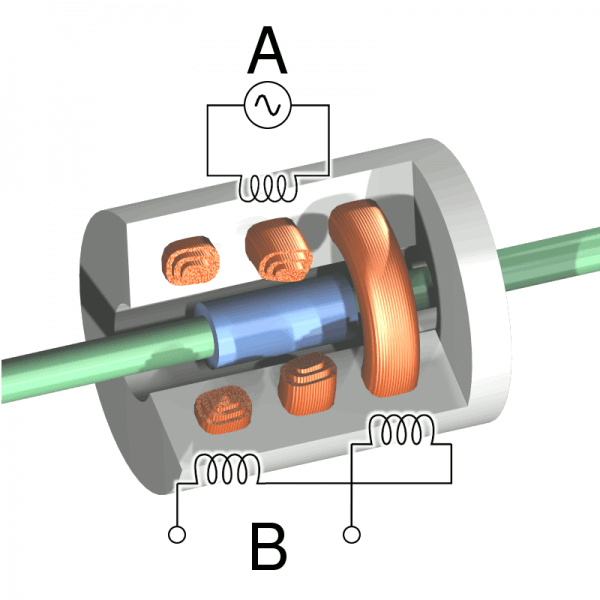
Figure 2: LVDT – Cutaway view with the primary coil A and the secondary coils B
Speed measurement
Principle of electrodynamics
The principle of electrodynamics is used in a relative speed sensor. It is based on the phenomenon of induction. In order to apply this principle a coil and a light permanent magnet is used. The magnet is fixed to the vibrating object. The magnet either moves contactless or it is guided within the coil.
Due to the movement of the magnet a voltage is induced in the coil. This voltage can be measured and it is directly proportional to the speed of the vibrations. The isolation of the wires is the only restriction for the maximum voltage. For example there are sensors with a working frequency range between 1 Hz and 2 kHz
Seismometer
Absolute speed can be measured with the Seismometer. The Seismometer consists of a seismic mass and a spring within a housing. Due to the inertia of the mass, there is a relative movement between the seismic mass and the housing, in case of vibrations. A coil, which is fixed to the housing, can be used cause induction.
Due to the movement of the mass, a voltage is induced in the coil. This voltage speed can be measured because it is proportional. Often attenuation equalization is installed in such a seismometer in order to avoid resonance peaks.
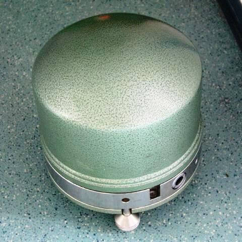
figure 3: Seismometer
In today’s seismometers the mass is fixed motionless in relation to the housing. Thus there is no voltage amplitude caused by motion of the seismic mass. However the force, that is needed to hold the mass in balance, is measured through voltage. Modern seismometers are able to register frequencies from less than 10-3 Hz up to 100 Hz. It is possible to detect movements in the range of about 1 nm and several centimetres. The principle of seismic mass can also be used in path and acceleration measurement.
Acceleration measurement
Piezoelectric sensor
Piezo-resistive sensor
Resistive sensor
The functional principle of the resistive sensor is the same as the one of the piezo-resistive sensor. The only difference is that the strain gauges are not built of materials that have a piezo effect. This leads to similar properties. But the measurable signal is lower.
Inductive sensor
The inductive sensor for acceleration measurement is based on the fact that the reaction force of the seismic mass can be converted into a path. Now the covered distance can be calculated through measuring the induced voltage and thus the magnitude and direction of the vibration can be ascertained. However this path-dependent measurement requires the sensor to be a lot bigger than comparable acceleration sensors.
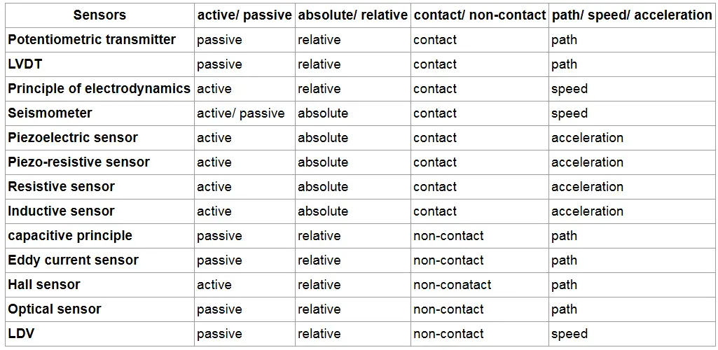
Vibration Sensors Characteristics