Inst ToolsInst ToolsInst Tools
  • Courses
  • Automation
    • PLC
    • Control System
    • Safety System
    • Communication
    • Fire & Gas System
  • Instrumentation
    • Design
    • Pressure
    • Temperature
    • Flow
    • Level
    • Vibration
    • Analyzer
    • Control Valve
    • Switch
    • Calibration
    • Erection & Commissioning
  • Interview
    • Instrumentation
    • Electrical
    • Electronics
    • Practical
  • Q&A
    • Instrumentation
    • Control System
    • Electrical
    • Electronics
    • Analog Electronics
    • Digital Electronics
    • Power Electronics
    • Microprocessor
  • Request
Search
  • Books
  • Software
  • Projects
  • Process
  • Tools
  • Basics
  • Formula
  • Power Plant
  • Root Cause Analysis
  • Electrical Basics
  • Animation
  • Standards
  • 4-20 mA Course
  • Siemens PLC Course
Reading: HART Communication Tutorial Part 3
Share
Notification Show More
Font ResizerAa
Inst ToolsInst Tools
Font ResizerAa
  • Courses
  • Design
  • PLC
  • Interview
  • Control System
Search
  • Courses
  • Automation
    • PLC
    • Control System
    • Safety System
    • Communication
    • Fire & Gas System
  • Instrumentation
    • Design
    • Pressure
    • Temperature
    • Flow
    • Level
    • Vibration
    • Analyzer
    • Control Valve
    • Switch
    • Calibration
    • Erection & Commissioning
  • Interview
    • Instrumentation
    • Electrical
    • Electronics
    • Practical
  • Q&A
    • Instrumentation
    • Control System
    • Electrical
    • Electronics
    • Analog Electronics
    • Digital Electronics
    • Power Electronics
    • Microprocessor
  • Request
Follow US
All rights reserved. Reproduction in whole or in part without written permission is prohibited.
Inst Tools > Blog > Communication > HART Communication Tutorial Part 3

HART Communication Tutorial Part 3

Last updated: August 15, 2016 8:33 am
Editorial Staff
Communication
1 Comment
Share
5 Min Read
SHARE

HART COMMUNICATION LAYERS

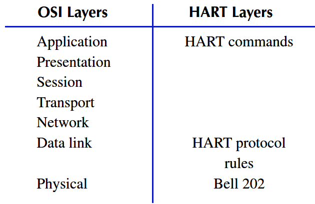
The HART protocol follows the seven-layer OSI (Open Systems Interconnection) protocol, although it uses only three layers: application, data link, and physical. The other four are not used, which is so for most of the field level protocols such as HART. The HART and the OSI protocol layers are shown in Table.

HART Layers vs OSI Layers

 Physical layer

HART uses an FSK physical layer that is based on the Bell 202 modem standard. It modulates digital “1” into 1200 Hz and “0” into 2200 Hz. This kind of modulation is robust and has very good noise immunity. A HART modem chip is used at both the sending and receiving ends for modulation and demodulation, respectively.

Frequency Bands for 4-20mA and HART Signals

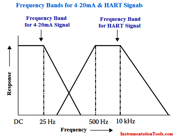
HART devices support both the conventional 4–20 mA current signal and modulated HART communications. These occupy different communication bands and are shown in Above Figure. Because of their noninterfering nature, as is apparent from Above Figure, both communications are possible simultaneously. The HART communication signal is filtered out by the analog devices and as such they remain unaffected by the HART signal. Thus, devices with 4–20 mA input or output work nicely in control loops.

 Data link layer

The HART message frame format, often called a HART telegram, is shown in Below Figure. It consists of nine fields.

Preamble is the first field in the message that is sent first, and it wakes up and synchronizes all the receivers of the connected devices in the network. The delimiter, a single-byte field, signifies the end of the preamble. The delimiter is a start field and its content denotes if the frame is a request from a master, a response from a slave, or a request from a slave in the burst mode. It also indicates whether the address used is a polling address or a unique ID.

HART Communication Data Link Layer

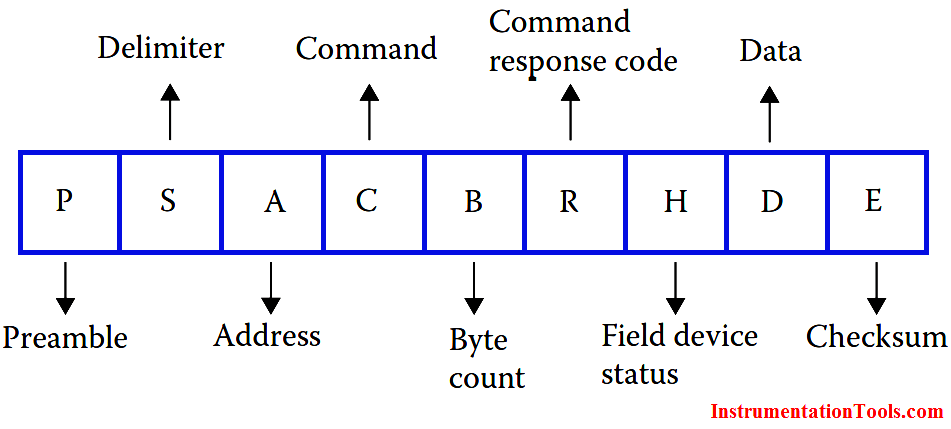
The address field that follows may be a single byte (short-frame format) for polling address or 5 bytes (long-frame format) for a unique ID address, already discussed in Tutorial Part 2.

The fourth field is the command field and is of single byte. It represents the HART command associated with the message. The data link layer does not interpret the same but passes (accepts) the same to (from) the application layer. The byte count is of single byte length and indicates how many more bytes are still left for the message to be completed, excluding the checksum. The receiver can thus check for the end of the message from the information provided by this field.

The response code is also single byte and is included only in response messages. This response field from the slave would indicate the type of error that occurred in the received message, if it was received erroneously. Correct message reception would also be indicated by this field. The field device status, a single-byte field, is included in response messages to indicate the health of the device.

The data field may contain from 0 to 24 bytes. Data is not interpreted in the data link layer and is merely passed to the application layer. The checksum is of single byte and of longitudinal cyclic redundancy check type. If the data is received correctly, the transmitting end checksum value would be identical to the receiving end checksum.

Application layer

HART commands are defined in the application layer of the HART protocol. The communication routines of the HART master devices and the programs are based on these commands. Commands from the master can seek for data, start-up service, or diagnostic information. The slave, in turn, responds by sending back the required information(s) to the master.

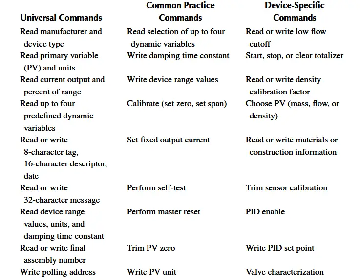
The HART command set includes three types of commands: universal commands, common practice commands, and device-specific commands. The host application may implement any of the command types for a particular application. A partial list of different types of HART commands is shown in Below Table.

HART Commands

Don't Miss Our Updates
Be the first to get exclusive content straight to your email.
We promise not to spam you. You can unsubscribe at any time.
Invalid email address
You've successfully subscribed !

Continue Reading

HART Communication Interview Questions and Answers
FF Function Blocks
AS-interface and DeviceNet Communication
Difference between Router, Switch, and Hub
What is Profibus? – A Comprehensive Guide for Beginners
Foundation Fieldbus Device addressing
Share This Article
Facebook Whatsapp Whatsapp LinkedIn Copy Link
Share
1 Comment
  • K M N S Kiran says:
    January 2, 2017 at 11:51 am

    Good explanation sir,
    We have HART 375 Filed communicator. We are facing issue, while going into HART application a blank screen appearing. Remaining settings like scratchpad, keyboard, display etc., are working fine. Please suggest for possible remedy.

    Reply

Leave a Reply Cancel reply

Your email address will not be published. Required fields are marked *

Stay Connected

128.3kFollowersLike
69.1kFollowersFollow
210kSubscribersSubscribe
38kFollowersFollow

Categories

Explore More

History of OPC Protocol
How are HART instruments Calibrated?
HART Communication Tutorial Part 5
Important Networking Interview Questions
Fiber Optic Cable Construction
Why Baud Rate is Important in Modbus Network?
Foundation Fieldbus Standard Function Blocks
Optical Fiber Cable – SC and ST Optical Fiber Connectors

Keep Learning

foundation-fieldbus-vs-profibus

Comparison between Foundation Fieldbus and Profibus

Foundation Fieldbus Interview Questions and Answers

Foundation Fieldbus Interview Questions and Answers

Profibus network

How Profibus Communication Works

Difference Between Ethernet IP and EtherCAT

Difference Between Ethernet IP and EtherCAT

Modbus scan

How Modbus Communication works

Fieldbus Segment

Basics of Foundation Fieldbus

Fieldbus Analog Input Function Block

WirelessHART Network Protocol

WirelessHART Network Protocol

Learn More

Level Measurement Objective Questions

Level Measurement Objective Questions

Smoke Detector Testing Procedure

Smoke Detector Testing Procedure

Analyzers Questions and Answers

Electron Probe Microanalyser Questions & Answers

Dew Point Method Humidity Measurement

Humidity Measurement Principle

Function Module in Siemens PLC

What is Function Module in Siemens PLC?

PLC Sequential Lights Control Example

PLC Timer Example: Sequential Control of Three Lights with Reset

Field Transmitter Installation

Cables and Cable Glands Questions and Answers

Relay Wiring

Animation of Electromagnetic Relay

Menu

  • About
  • Privacy Policy
  • Copyright

Quick Links

  • Learn PLC
  • Helping Hand
  • Part Time Job

YouTube Subscribe

Follow US
All rights reserved. Reproduction in whole or in part without written permission is prohibited.
Welcome Back!

Sign in to your account

Username or Email Address
Password

Lost your password?