This is a PLC Program for heating liquid in the tank by heater.
Tank Heating Control
Problem Description
Controlling the heating process for the liquid in the tank.
Implement a PLC program for this application using ladder diagram language.
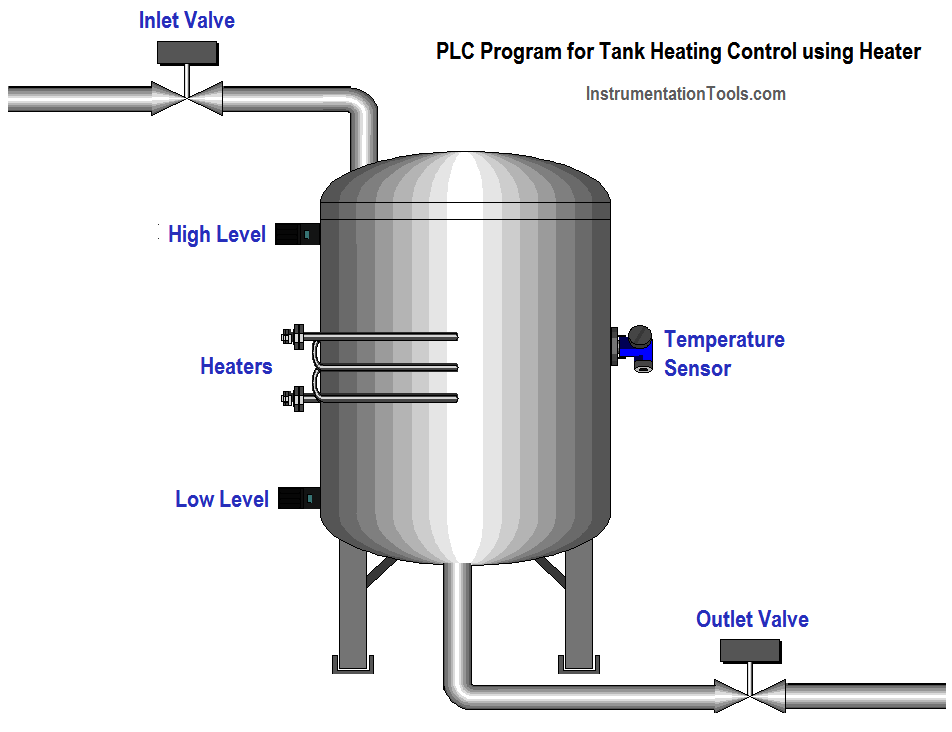
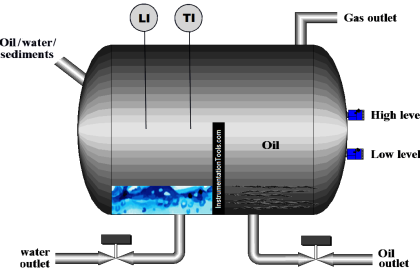
Problem Diagram
Problem Solution
In this system, we will consider S7-300 PLC and TIA portal software for programming.
In this system two sensors are used for level measurement in the tank, heater is used for material heating purposes in the tank.
We used a temperature sensor (it can be RTD or thermocouple) also for temperature measurement in the tank.
Two valves are used for the material inlet and outlet. The inlet valve is used for feeding the tank and the outlet valve for discharging the tank.
If the system detects a low level, the system will start to feed the tank. The feeding cycle will be OFF when the tank detects a high level.
After the high-level, the system will start the heating process till set temperature.
Inputs/Outputs List
Inputs List
- START PB :- I0.0
- STOP PB :- I0.1
- Low level switch :- I0.4
- High level switch :- I0.3
Outputs List
- Inlet valve :- Q0.0
- Heater :- Q0.1
- Outlet valve :- Q0.2
Memory List
- Master coil :- M0.0
- Actual temperature :- MW12
- Set temperature :- MW14
PLC Program for heating liquid in the tank by heater
Logic Description
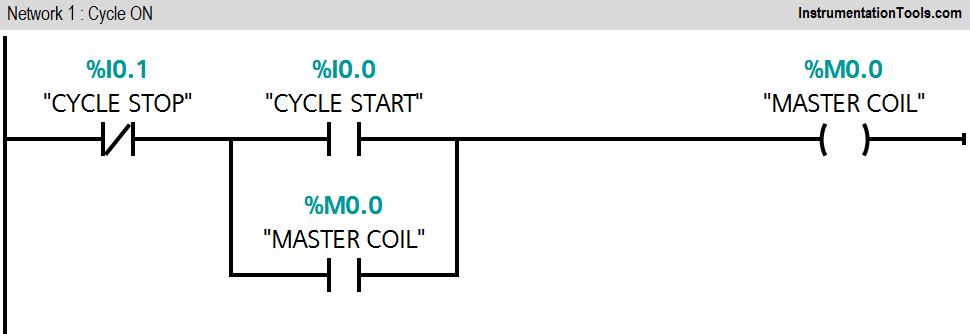
Network 1:
Master coil (M0.0) will start when START PB (I0.0) will be pressed and cycle can be stopped by pressing STOP PB (I0.1).
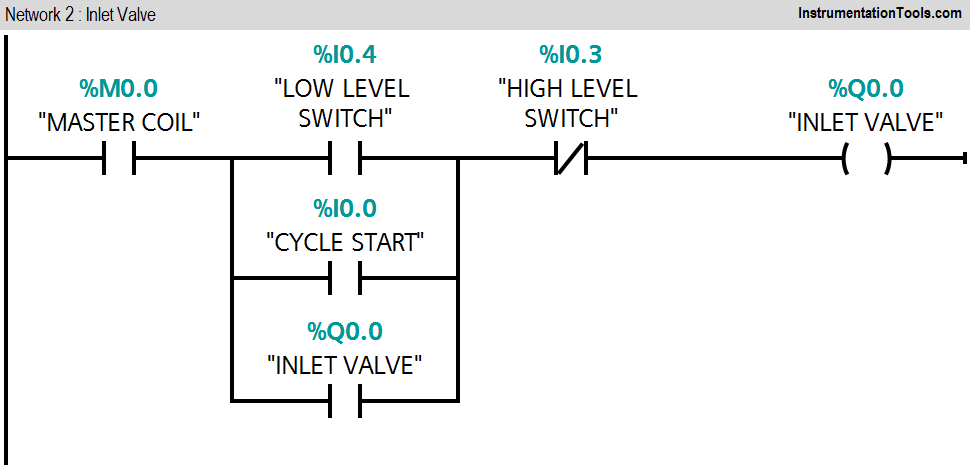
Network 2:
When low level switch (I0.4) is detected, inlet valve (Q0.0) will be ON.
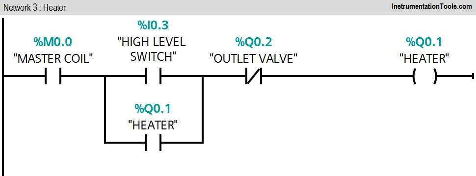
Network 3:
When high level switch (I0.3) is detected, heater (Q0.1) will be ON.
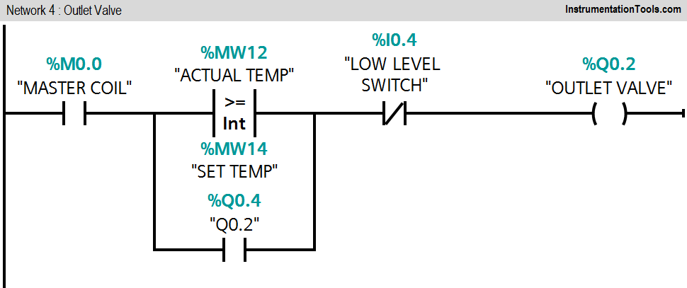
Network 4:
If actual temperature (MW12) is greater than set temperature (MW14), outlet valve (Q0.2) of the tank will be ON.
Note :- Above application may be different from actual application. This example is only for explanation purpose only. We can implement this logic in other PLC also. This is the simple concept of heating the material in the tank as per requirement in industry, we can use this concept in other examples also.
All parameters considered in example are for explanation purpose only, parameters may be different in actual applications. Also all interlocks are not considered in the application.
Result

If you liked this article, then please subscribe to our YouTube Channel for PLC and SCADA video tutorials.
You can also follow us on Facebook and Twitter to receive daily updates.
Read Next:
- Liquid Level Switch Control Logic
- PLC Seperate Different Size Objects
- Control Level of Series Tanks
- PLC Water Level Control
- Selective Execution of Application


The above example is a very crude example of “temperature control” as the temperature of the liquid will not be controlled at the set value. It will instead rise above the set point and fall below the set point.
The variation between the highest and lowest temperatures that will be experienced will depend on the power rating of the heater, compared to the cooling of the vessel. It true temperature control is required, then PID temperature control should be used in the program.
I have no experience but I would like to create simulator supervisors and use this example for academic purposes .. thank you very much
ITS NOT WORKING AS PPER the ladder diagram.
the nt:-2 the o/p will dependent upon high level sensor :”Q0.0″
Thank you it helps me a lot.