In its simplest form, a thermocouple is nothing more than a pair of dissimilar-metal wires joined together. However, in industrial practice, we often must package thermocouples in a more rugged form than a bare metal junction.
For instance, most industrial thermocouples are manufactured in such a way that the dissimilar-metal wires are protected from physical damage by a stainless steel or ceramic sheath, and they are often equipped with molded-plastic plugs for quick connection to and disconnection from a thermocouple-based instrument.
A photograph of a type K industrial thermocouple (approximately 20 inches in length) reveals this “sheathed” and “connectorized” construction:
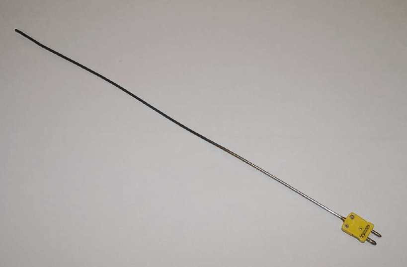
The stainless steel sheath of this particular thermocouple shows signs of discoloration from previous service in a hot process. Note the different diameters of the plug terminals. This “polarized” design makes it difficult (Note) to insert backward into a matching socket.
Note : It should be noted that no amount of engineering or design is able to completely prevent people from doing the wrong thing.
I have seen this style of thermocouple plug forcibly mated the wrong way to a socket. The amount of insertion force necessary to make the plug fit backward into the socket was quite extraordinary, yet this apparently was not enough of a clue for this wayward individual to give them pause.
Industrial-grade thermocouples are available with this miniature style of molded plug end as an alternative to the larger (standard) plug. Miniature plug-ends are often the preferred choice for laboratory applications, while standard-sized plugs are often the preferred choice for field applications.
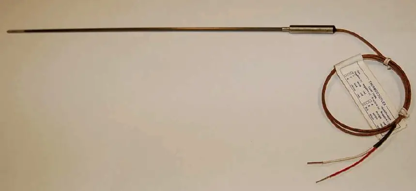
Some industrial thermocouples have no molded plug at all, but terminate simply in a pair of open wire ends. The following photograph shows a type J thermocouple of this construction:
If the electronic measuring instrument (e.g. temperature transmitter) is located near enough for the thermocouple’s wires to reach the connection terminals, no plug or socket is needed at all in the circuit.
If, however, the distance between the thermocouple and measuring instrument is too far to span with the thermocouple’s own wires, a common termination technique is to attach a special terminal block and connection “head” to the top of the thermocouple allowing a pair of thermocouple extension wires to join and carry the millivoltage signal to the measuring instrument.
This next photograph shows a close-up view of such a thermocouple “head”:
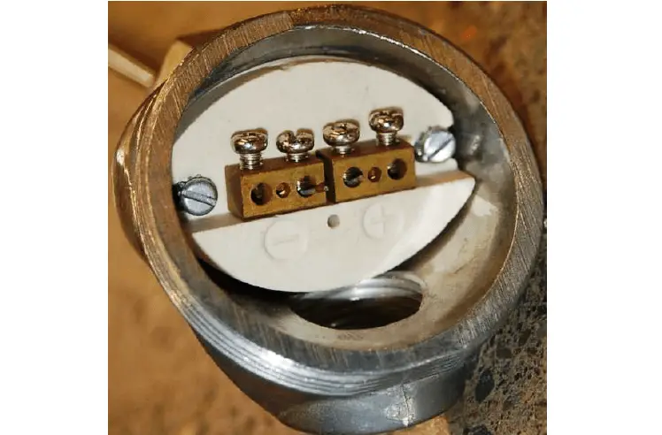
As you can see from this photograph, the screws directly press against the solid metal thermocouple wires to make a firm connection between each wire and the brass terminal block.
Since the “head” attaches directly to one end of the thermocouple, the thermocouple’s wires will be trimmed just long enough to engage with the terminal screws inside the head.
Both brass terminal blocks are mounted on a ceramic base, the purpose of the ceramic being to help equalize the temperatures between the two brass blocks while still maintaining electrical isolation.
This assembly is sometimes referred to as an isothermal terminal block because it acts to keep all connection points at a common temperature (“iso-thermal” = “same-temperature”).
A threaded cover on the head provides easy access to these connection points for installation and maintenance, while ensuring the connections are covered and protected from ambient weather conditions the rest of the time.
Thermocouple wires are most often manufactured in solid form rather than stranded form.
A common mistake made with thermocouple wires is for technicians to crimp compression-style terminals (“lugs”) onto the solid wires.
While this may form a usable connection at first, compression-style terminals are simply unable to maintain adequate compression when applied to solid wire of any type, thermocouple wire included.
Over time, solid wires will loosen inside compression terminals leading to circuit problems.
In the case of a thermocouple circuit, bad wire connections lead to a situation where the receiving instrument “thinks” the thermocouple has failed open.
This situation is commonly called burnout, referring to the phenomenon where a thermocouple junction fails open from being “burned out” by excessive temperature.
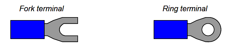
You will most often find compression terminals (improperly) applied to solid thermocouple wire tips where those wires must terminate under the head of a screw.
Compression terminals are correct to use in applications where stranded wire terminates at a screw head, but not solid wire.
The proper termination technique for solid wire under a screw head is to wrap the solid wire in a semi-circle and directly clamp it under the screw head.
At the other end of the thermocouple, we have a choice of tip styles.
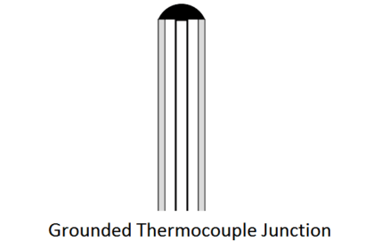
For maximum sensitivity and fastest response, the dissimilar-metal junction may be unsheathed (bare). This design, however, makes the thermocouple more fragile. Sheathed tips are typical for industrial applications, available in either grounded or ungrounded forms:
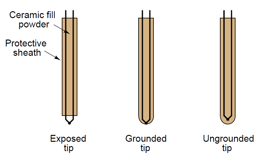
Grounded-tip thermocouples exhibit faster response times (Note) and greater sensitivity than ungrounded-tip thermocouples, but they are vulnerable to ground loops: circuitous paths for electric current between the conductive sheath of the thermocouple and some other point in the thermocouple circuit. In order to avoid this potentially troublesome effect, most industrial thermocouples are of the ungrounded design.
Also Read : Temperature Sensors Interview Questions
Note : Grounded thermocouples often have thermal time constant values less than half that of comparable ungrounded thermocouples.
Exposed-tip thermocouples are even faster than grounded-tip, typically by even larger ratios than grounded-tip thermocouples are to ungrounded thermocouples.
Credits : Tony R. Kuphaldt – Creative Commons Attribution 4.0 License