This is a PLC Program for Latching and an unlatched circuit for output.
PLC Latching and unlatching Circuit
Problem Description
In some conveying systems, the operator fills the tank manually by operating the water pump manually.
In this situation operator waits when the tank is being filled because when the tank reaches to high level, the water pump should be stopped.
Also water pump should remain in ON condition until the tank reaches a high level.
For example, we consider a manual water conveying system in this article.
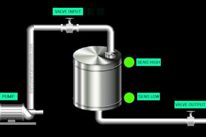
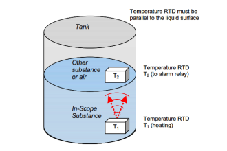
Problem Diagram

Problem Solution
In this example, we consider one storage tank for water and use one water pump for tank filling.
We also use one level sensor for high level and control panel for operator.
Here START PB for enabling the motor so we can feed the water in the tank, for stop motor we use STOP PB.
Level sensor for detection of High level so when tank becomes full, high level sensor will be activated and stops the water pump.
For this sequence we will use SET and RESET instruction for latching and unlatching the water pump.
We can make this circuit by sing relays.
In application there one manual discharge valve only for discharging the tank manual. We will not consider in or logic.
PLC Inputs List
- START PB : I0.0
- STOP PB : I0.1
- HIGH LEVEL SENSOR : I0.2
- LOW LEVEL SENSOR : I0.3
PLC Outputs List
- WATER PUMP : I0.0
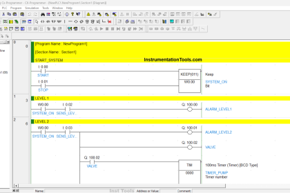
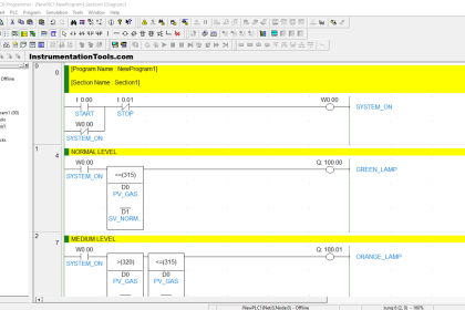
PLC Ladder diagram for Latching and unlatched circuit

Program Description

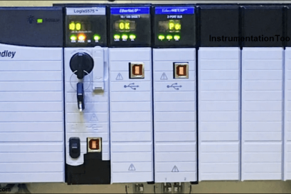
- For this application we use S7-1200 PLC and TIA portal software for programming. We can make this circuit or logic with relay also.
- This circuit or logic known as latching and unlatching circuit or logic.
- We will write logic for water pump in Network 1. Here we use NO contact of START PB (I0.0) for enabling the water pump (Q0.0).
- By using SET instruction water pump output coil (Q0.0) will be latched.
- Add NO contact of LEVEL LOW SENSOR (I0.3) in series with the water pump output (Q0.0).
- Water pump should not start if tank is full. so for safety purpose use one NO contact of LOW LEVEL SENSOR (I0.3) in series after START PB (I0.0) in Network 1.
- Now HIGH LEVEL SENSOR (I0.2) will be detected after some time of pump running and in this case water pump (Q0.0) should be stopped automatically. For that purpose we need to unlatch the circuit.
- We will write logic for unlatching circuit in Network 2. In this case, we take No contact of HIGH LEVEL SENSOR (I0.3) for unlatching the circuit by using RESET instruction.
- Add one NO contact of STOP PB (I0.1) in parallel connection, so operator can unlatch the circuit by pressing STOP PB (I0.1).
- Here we latch circuit by SET instruction and unlatch with RESET instruction.
Runtime Test Cases

Note: The above PLC Logic provided for basic idea about application of PLC Program for Latching and unlatching Circuit. The Logic is limited and not complete application.
If you liked this article, then please subscribe to our YouTube Channel for PLC and SCADA video tutorials.
You can also follow us on Facebook and Twitter to receive daily updates.
Read Next:
- PLC Programming Questions & Answers
- Sequence of Conveyors with Interlock
- Motor Operation based on Time Cycle
- PLC Tank Heating Control using Heater
- Heating and Mixing of Products using PLC


Thank you .
These kind of examples help to learn PLC programming .Kindly continue and give harder examples.
excelente artigo!
Please help me for my activity. Its difficult like me as first timer.
Here is the problem.
When you press Push Button (PB1) – X21 the output bulb (YO) will lit… When you release the PB1 the output bulb will off.